

- Messages
- 7,908
- Name
- Terry
- Edit My Images
- Yes
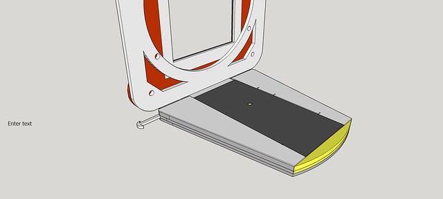
Rather than use a plate on the bottom with a captured thread and rubber surface.It would probably be stronger and certainly far easier to shape and weld on a layer of plastic, to form a camera plate, to fit a Swiss type QR. It would also have none of the thread stripping or thread insert problems and weaknesses. Ant also no tendency to rotate.
I have done it with a shaped piece of thick brown circuit board material. You can also put a strong fine thread into that material, so it could easily be screwed on for belt and braces security.
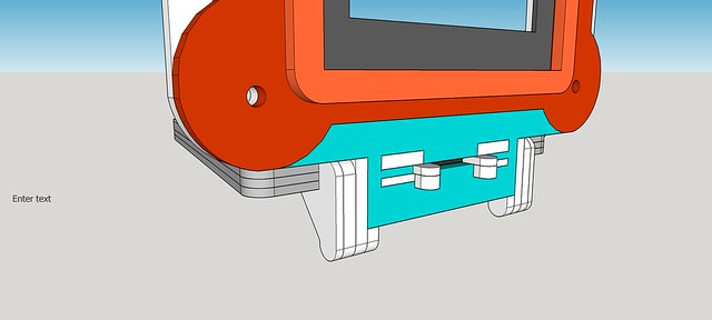
But it would be easy to satisfy yourself that your acrylic sheet would be easily strong enough. Dovetail clamping is mostly compression and so is incredibly strong in almost any solid material.
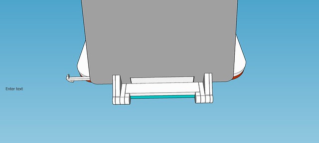
If you really must have a screw mount. You could always fix one in the centre of the Swiss type plate you make.
for the rare occasions you might want to mount that way.
I have done it with a shaped piece of thick brown circuit board material. You can also put a strong fine thread into that material, so it could easily be screwed on for belt and braces security.
But it would be easy to satisfy yourself that your acrylic sheet would be easily strong enough. Dovetail clamping is mostly compression and so is incredibly strong in almost any solid material.
If you really must have a screw mount. You could always fix one in the centre of the Swiss type plate you make.
for the rare occasions you might want to mount that way.
Last edited:

 catch
catch catch2
 Too "custom"? ;0)
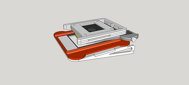
 First assembly
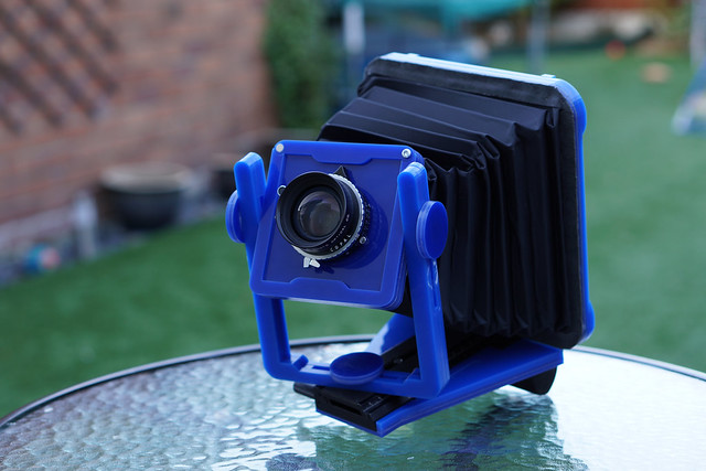 First assembly
 First assembly
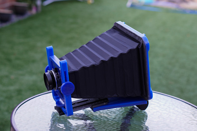 First assembly - Telephoto
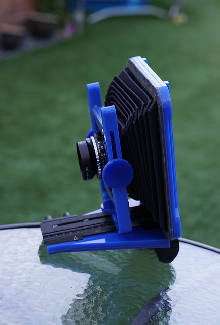 First assembly - Wide Angle
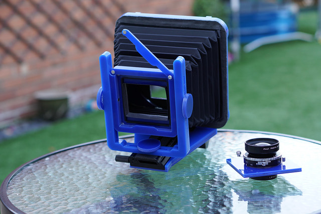 First assembly
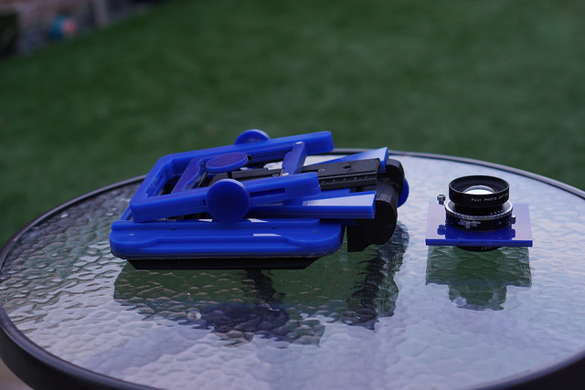 First assembly - DIsassembled
 First assembly - Rear - Landscape
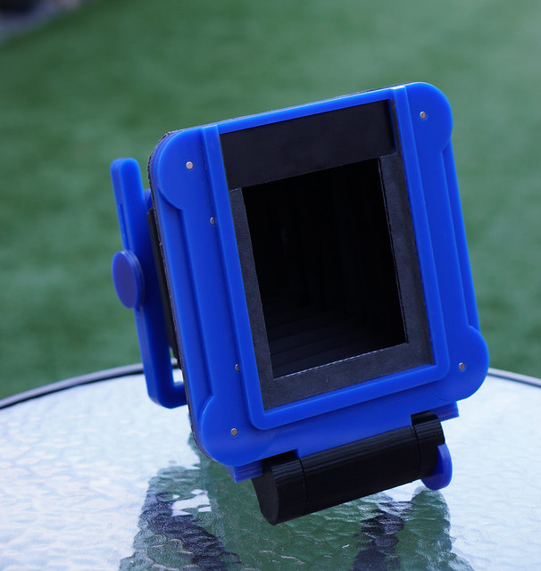 First assembly - Rear - Portrait
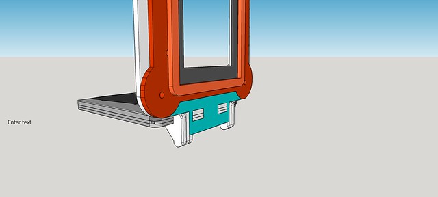
 New Hinge and Spring Clip - Open
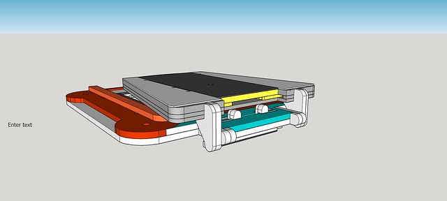 New Hinge and Spring Clip - Closed


 All
All 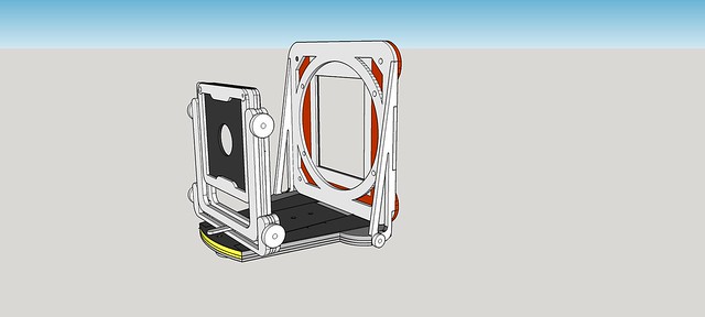 Technical Standard Overview
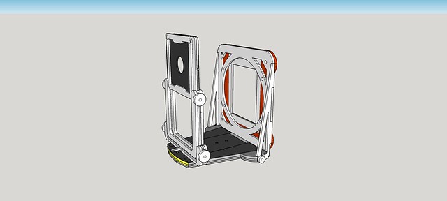 Technical Standard - 75mm Rise
 Technical Standard - 25mm Fall
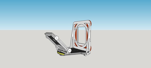 Technical Standard - 45mm Front Tilt
 Technical Standard - 45mm Rear Tilt
 Technical Standard - 55mm Right Shift
 Technical Standard - 45 Degree Right Swing