Barn Door Tracker

Messages
270
Name
Ken
Edit My Images
Yes
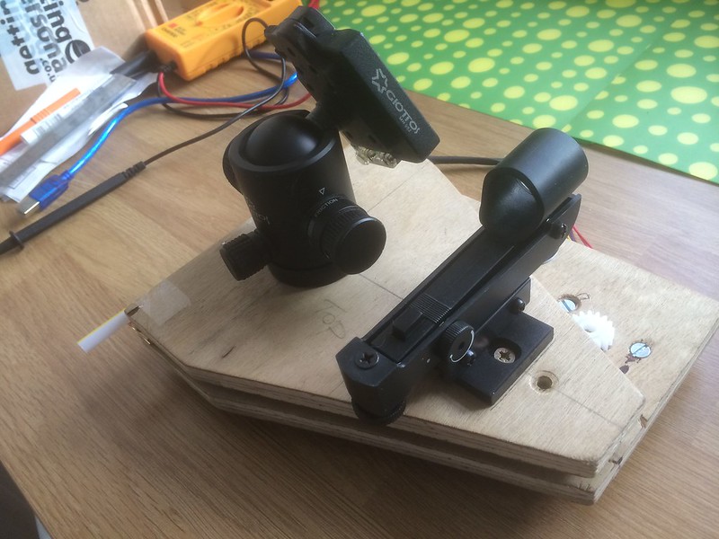
For those of you who are interested in night time/celestial photography I have recently finished building a barn door tracker which allows for longer exposures of the night sky by tracking the movement of the stars. I can do a full write up on the build depending on replies for those interested.
Total cost was around £50 as opposed to the hundreds for a dedicated equatorial mount.
 
Last edited:
Nice one, always been interested in these - yeh feel free to stick up workings of your DIY project, sounds great
 
*Googles barn door tracker*.............

Looks interesting....would definitely like to see your project. (y)
 
I have done a full write up on POTN so when I get time I will cut and paste it here for those that are interested. Saves me having to write the whole thing out again.
 
I mainly do landscape photography but recently have found myself looking at more and more astronomy and celestial images so I decided I would like to have a go myself. From the research I have done I have found that it can be quite expensive so I decided I would have a go at making my own barn door Tracker. If it works and I find I like astrophotgraphy then I will probably invest in proper gear designed for the purpose.

I decided to follow Gary Seroniks plans here:
http://www.garyseronik.com/?q=node/52

So I won't go into great detail about the basics. All I will say is that I made it with a few hand tools I had around the house and a lot of patience. I have no work shop, garage or work bench.
My main problem was sourcing materials in the UK. Most of which I sourced on ebay and local DIY stores such as B&Q, after some research.


I initially decided with a 12V DC motor and purchased one from Amazon along with a PWM controller board from ebay. I then did some research and found that these motors can lose power as the batteries die, which is not good as you must have a constant of 1 RPM at the drive rod, so I decided to look for another option. By the way none of these items have arrived yet 1 month after purchase :roll eyes:

After some research I decided to use a 5V stepper motor and Arduino from ebay:
http://www.ebay.co.uk/itm/1611629026...84.m1497.l2648
http://www.ebay.co.uk/itm/1310150045...84.m1497.l2648

My initial concerns with this combination were:
a) would the motor be powerful enough due to it's small size and
b) I know nothing about programming and the Arduino requires some code uploading to drive the motor at the correct RPM.

More on these later….
 
Last edited:
Now the brass rod.
I was concerned that I wouldn't be able to source the correct size here in the UK as Gary Seronik states he used 10-32 thread brass rod. I couldn't find anywhere that supplied this in the UK. Again I did some research and found that M5 metric is the same. So I ordered 2 x 500mm lengths from ebay.
The bending of the rod was quite easy and I did this by hand using a full 500mm length before cutting it to the required length..

 
The gears

I searched quite a bit on the internet and found the following company that supplied them:
http://www.bearingshopuk.co.uk/delrin-3262-c.asp

I ordered a 1 mod 16 and 64 tooth delrin gears.

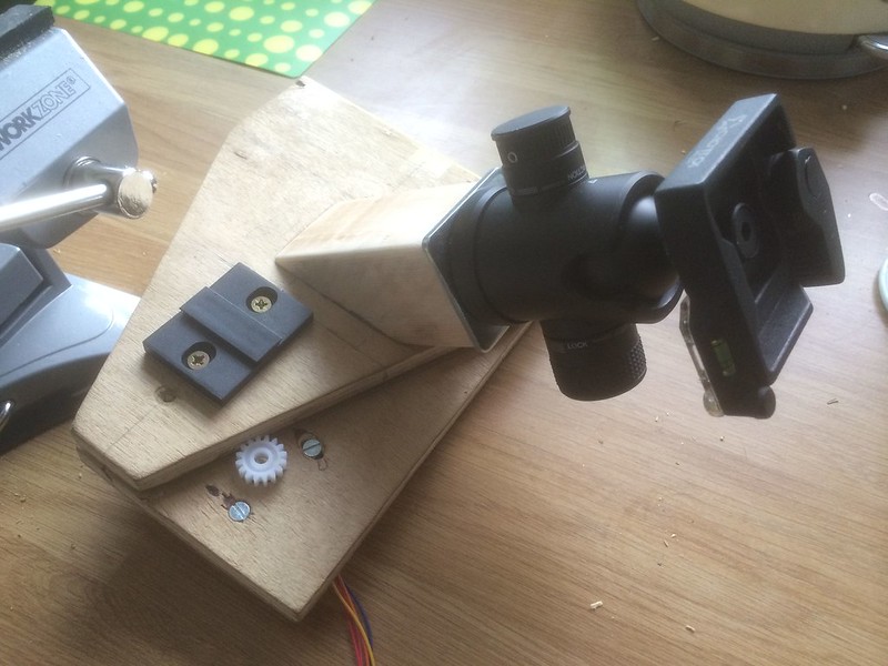
I had to do the same as Gary Seronik with the large 64 tooth gear. That is file the hole to make the blind well nut fit into it. I used a small file set purchased from B&Q to do this, cost around £7.00. With a bit of patience I managed to get a really tight fit. The plastic is harder than it looks and it took some effort to file it to the required bore.
 
Whilst waiting for items to be delivered I decided to do a partial assembly.
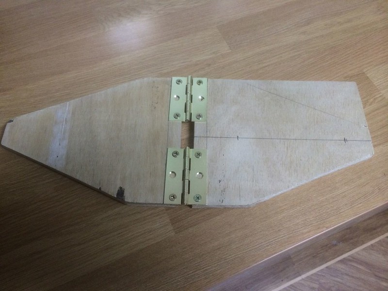
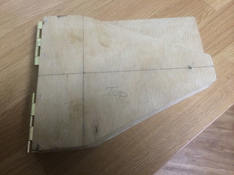
The holes for the brass rod to go through on the plywood are measured from the centre of the hinges and this is a critical measurement.
Note on the pictures that the 64 tooth gear is slightly bigger than the base so anyone making one of these may want to make the base slightly larger. The crucial point is the positioning of the hole for the brass rod to go through.


The 5V stepper motor and Arduino arrived so I decided to attach the motor to the base.
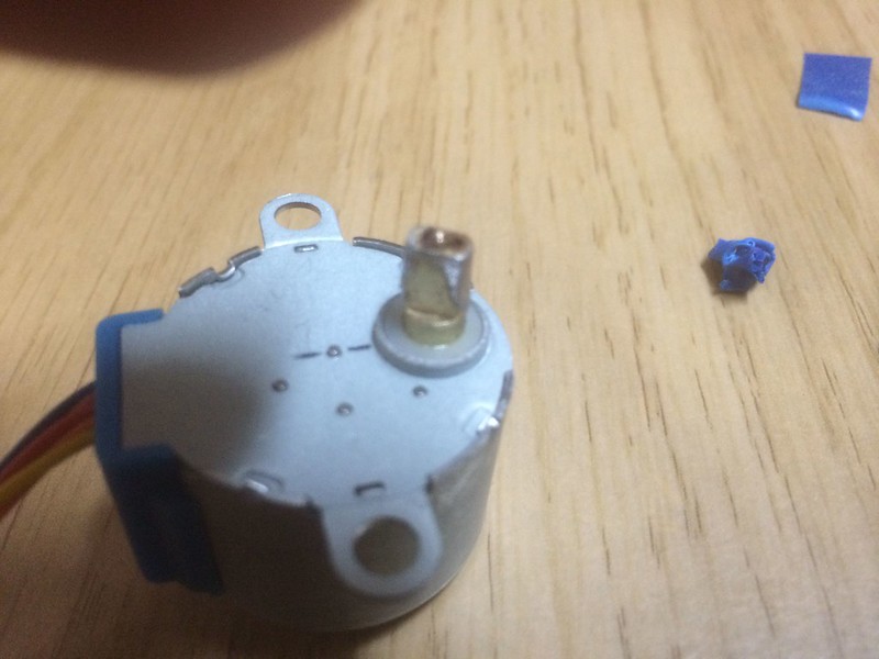
THis is where I had the most difficulty. The drive shaft on the motor isn't long enough to reach through the ½ inch plywood and the 16 tooth gear isn't long enough to fit over the drive shaft so I decided to cut a ¼ inch recess in the plywood to fit the motor into. Like I said previously I have no workshop or bench so I did this with a 10mm wood bit marked with a piece of tape on the bit to give me the depth. Once I had drilled this out I then used a small swiss army knife to clean the recess out. This is where I drew first blood
icon_cry.gif
and sliced the end of my finger open
icon_evil.gif


One point I will make here is that the bore in the 16 tooth is slightly too large to get a snug fit on the motor drive shaft so I had to improvise a little. I added some solder around the end of the drive shaft to make it bigger then filed it to get a tight fit when the gear was pushed onto it.

 
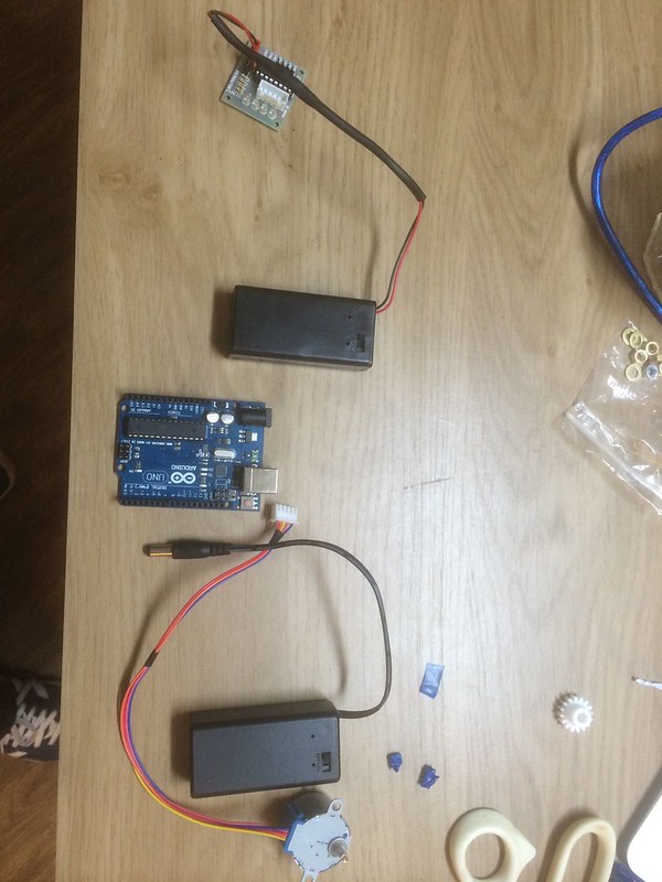
The 5v Stepper motor comes with it's own drive board which has to be connected to the Arduino to receive the required signals to drive the motor. I checked the power supply fitting on both the motor and Arduino and then ordered the appropriate 9V battery cases and fittings from ebay. The Arduino fitting sourced without problem but the motor board I had to order the fitting for the board and a separate 9V battery case then connect the two together.

 
Now for the fun part, programming the Arduino. I spent about 2 weeks researching this and still not sure how or what I did but I got it working perfectly. The motor has to turn at 4RPM to make the drive bolt on the brass rod turn at 1RPM through the gears.
It is quite easy to upload a program to the Arduino using the usb cable supplied with it.
To do so you need the Arduino IDE software readily available on the Arduino site. At first I just tinkered with various programs that I downloaded from the web. There are loads out there with a lot of tutorials.
I just wanted to get the hang of using and changing the motor parameters. Arduino programs are known as sketches.
Next I downloaded quite a few motor sketches and then tried to change them for my requirements.
I eventually found one, which after changing a few things in the sketch, worked perfectly.
From what I have learned about the programming and the bits to change in the sketch I found that the parts to change in the sketch just didn't make sense and the motor wouldn't turn at the required speed. I eventually got there by trial and error and it works perfect at the required speeds.
I then tested the motor and gears attached to the tracker using the stop watch on my laptop and the larger gear turns at exactly 1RPM.
icon_biggrin.gif

I have this code available if anyone requires it.
 
Next I assembled everything. I already have a Manfrotto 405 pro geared head with a spare plate that I attached to the underside of the tracker. I already had a spare Giottos ball head that I attached to the top of the tracker. I then carried out some more testing and and the motor worked flawlessly, turning at the correct 4RPM.

 
The next step was to test the tracker under load. I attached my Canon 5D3 and 24-40 L lens, quite a heavy combination. Once again everything was perfect. This is when I thought the stepper motor would struggle.

 
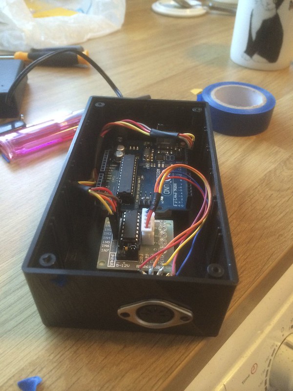
Now to tidy things up. I ordered a small plastic project box from ebay and set about installing the motor drive board and Arduino into it.


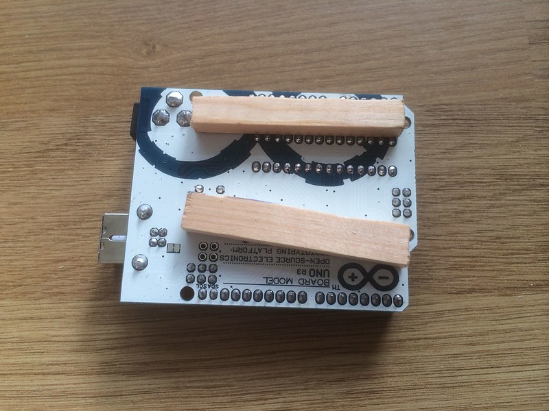
I cut 2 small pieces of wood and used double sided tape to attach them to the underside of the Arduino and then stuck the Arduino in place in the box. My thinking behind this was to allow a bit of airflow around the Arduino.


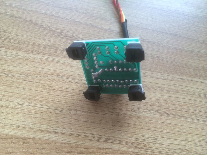
I raised the motor driver board by cutting the ends from large cable ties and then using double sided tape on these.

 
I wanted the project box to be completely plug and play so to speak with no wires dangling out of it. To do this I had to cut the wires from the motor as the motor plugs directly into the driver board that is supplied with it. I purchased a 5 pin male/female chassis mount plug to do this. A bit of soldering is required to do this. I used a portable gas soldering iron with a fine tip to do this. This is something I had in my toolbox.


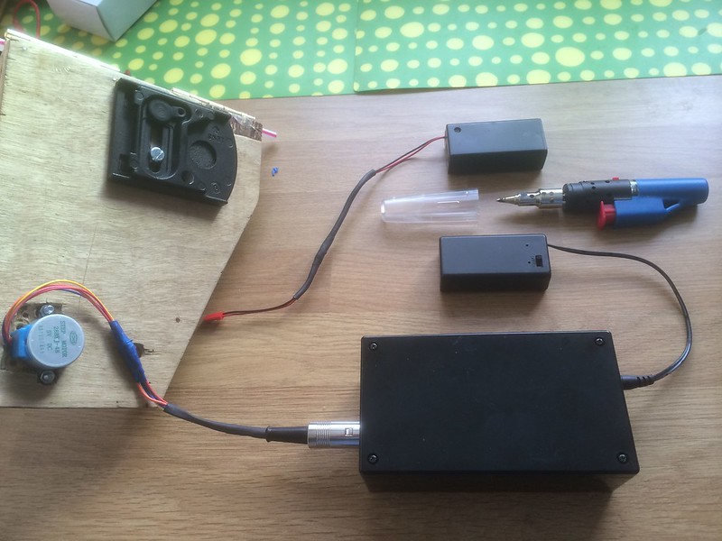
This image shows the project box with the Arduino power supply and the motor cables with plug attached to the box. I have also shown the soldering iron I used. You can see the power supply for the motor driver board in the picture. I have ordered the same type of connection as the 9V Arduino power supply. Both male and female plugs. I am waiting for them to be delivered. More cutting of wires and soldering to carry out. Once this is carried out the project box should be completely plug and play. I intend to attach it to the underside of the tracker using velcro strips.

 
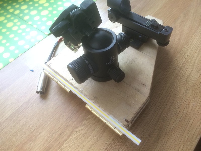
Whilst waiting for bits and pieces to be delivered I purchased a celestrion red dot Star finder and attached it to the top of the tracker, parallel to the hinges. I then aligned this with the hinges as per instructions that came with the finder. I used jupiter to do this, so now the red dot should be aligned with the tracker hinges.


I used a straw taped to the hinges, looked through the straw and centred jupiter so that the hinges were aligned with jupiter. next I aligned the red dot with jupiter.

 
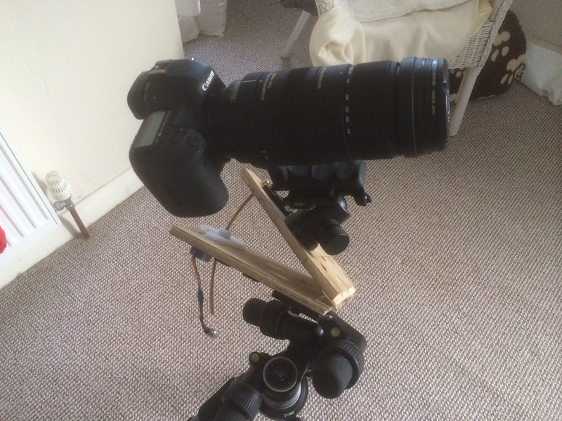
I have since tested the tracker with my 5D3 and sigma 120-400 lens on, as this is my heaviest combination. Everything works as it should and the motor turns at 4RPM constantly, giving 1RPM at the drive bolt on the brass rod. I must say I had my doubts about this motor as it is so small. The proof in the pudding will be field tests I suppose.

That's all I can say for now, I am still waiting for a few bits just to tidy things up.
If anyone has any questions or needs more information then please don't hesitate to ask.

All I need now are some clear skies and see if I have the astro bug.
Not hopeful on the clear skies at the moment as the UK is being battered by one storm after another.
 
The motor was £5 (Ebay)
The Arduino was around £13 (Ebay)
the brass rod was about £8 (Ebay)
Nuts and bolts came to about £7 frame various ebay sources and B&Q
2 x 9V battery cases £3 each (Ebay)
Bread board jumper wires £3.50 (Ebay)
Plastic project box £5 (Ebay)
5 pin male/female chassis plug £3.50 from Maplins
Delrin gears were about £7
few other bits and pieces
So i would say a little over £50

I did buy some other odd and ends but never used them as I kept changing my mind as I went along.

I must say I have enjoyed myself doing this. I am thinking of making 2 new wood bits with better measurements and a bit tidier.
 
I set everything up again and placed my 5D3 and sigma 120-400 lens on the tracker and found that I couldn't get a high angle with this combination due to the camera catching on the edge of the top plywood platform. I moved the ball head to the location shown below and now everything is working fine.


If anyone would like to have a go at making one of these please don't hesitate to ask. I'd be glad to help out.
I am going to make the plywood platforms again but a bit tidier this next time. It should be a lot easier next time due to lessons learned making the first one.
 
Very impressive! and a practical solution to the off the peg variety that are awfully expensive. I still have several purely hand driven trackers I built many years ago in various forms as my "light bulb moments" gathered pace.
Since moved on to a computer controlled eq mount that was even more expensive! Astro photography has grown enormously as digital cameras became available to consumers.
Your mention of motors/weight concerns are an obvious problem though balance can eliminate such problems to a large degree, getting a good balance can let even a small stepper motor have an easy life.

Good luck with your new kit and clear skies and show us your images.

My tracker though not used for sometime due to many other interests.:(
 
Last edited:
Fabulous Ken, nice job that - have you had a chance to use it yet, be interested in the results :)

cheers,
drew
 
Yes Drew, I did some testing in the back garden the other night. Nothing brilliant as I was just after testing the tracking abilities. The tracking was spot on up to 3 mins. I didn't test any longer than that, maybe next time. I have made a few modifications due to minor problems when testing.
I will post up the results later.
 
A few pics testing the tracker in the garden the other night. I didn't nail the focus but I wasn't really bothered about that just yet. I wanted to see how well the tracker would track the stars. I lined it up with The celestial north pole and tracked the brightest star I could see which was Alkaid ( the last star in the handle of the plough/big dipper ).
Like I said they are out of focus but no evidence of trailing. The movement of these stars was at a 45 deg angle in the sky so no obvious sign of trailing in the images. The images are straight out of the camera, no editing.

1 min exposure


2 min exposure


3 min exposure


All at iso 800, F 5.6 with canon 5D3 and sigma 120-400 OS DG lens.
 
I still had some problems with stars that were higher in the sky. I tried to line up with cassiopeaia but I couldn't get the angle due to the equipment catching the tracker so I have made some adjustments today.

 
What exposure time did you use on those photos, pity they are out of focus, is that a problem with astro photography?
 
It tells you in the post above each image. 1, 2 and 3 minutes.
It can be difficult to a newcomer like me to get the focus right, I just need to keep practicing.
 
Great little project. Time to head off to a dark sky area I think.

There is a lot of electronics for the stepper motor. what steps does the motor move in?
I also couldn't see the drive mechanism, is the brass rod threaded?
I'd love to see your drawings - I could try to make one on my mates 3d printer
I used the plans found here: http://www.garyseronik.com/?q=node/52
The stepper drives the small cog at 4 RPM which in turn drives the larger cog at 1 RPM. The brass rod is M5 threaded. There is a small M5 blind nut inserted in the larger cog which is threaded onto the brass rod. As the cogs turn they push the rod up.
I think this particular motor has 4096 steps per 1 revolution.
 
Did some more testing tonight but used my 24-70L F2.8 lens. I have edited the 2 images below in photoshop. I managed about half an hour before the clouds rolled in.
same location as the previous images, my back garden which is in a heavily light polluted area. I made a better job of the focusing on this occasion.

The Plough/Ursor major
2 min exposure at 35mm, Iso 800, F5.6


Cassiopaei (in there somewhere )
5 min exposure at 35mm, Iso 800, F5.6
Some very slight trailing in this image when zoomed in.
 
What a great write up, i'm sure it'll be helping a lot of people out, looking like its doing a perfect job with the 2 images above
 
That 5 min exposure is pretty good after zooming in, think your on the right track (excuse the pun) longer the exposure more chance of light pollution creeping in. With focus if using a manual lens set to the infinity mark on the barrel as a starting point or set focus before dusk on a distant land based object...guessing you already know that anyway. After finding optimal focus mark the lens barrel for reference. Clear skies.
 
Orion Nebula last night. Obviously some vibration on this that I need to work out. 10 x 30 sec subs and 10 x 30 sec darks stacked in DSS. Iso 1600 F5.6 @ 400mm . Still a lot to learn with imaging and processing afterwards. Not too bad for a first attempt using the barn door tracker.

 
Can you make me one? ;) Looks great, i wish i could knock something up like that. :)

Orion Looks great just a shame there were some vibrations, is the mount sturdy enough with the extra load? Try hanging a heavy'ish weight to the bottom of the mount, may help.
 
Thanks Machete. If live local to myself and supply all the materials I will certainly have a go. I enjoyed this little project.
The mount is actually more stable than I thought, the image above was just due to my inexperience and stacking abilities with deep sky stacker.
I have binned the images with the vibration on and reprocessed the it again, see below...

 
For those of you who are interested in night time/celestial photography I have recently finished building a barn door tracker which allows for longer exposures of the night sky by tracking the movement of the stars. I can do a full write up on the build depending on replies for those interested.
Total cost was around £50 as opposed to the hundreds for a dedicated equatorial mount.

You'll be doing this kind of thing soon:

 
Back
Top