While the laser cutter is still out of action (they've gone through 3 tubes now!), I'm keeping my mind active working on the idea of a through the lens light meter. The main benefit of this is that it would take into account bellows extensions/filters etc. Obviously, I could just build it into another plate that drops into place instead of the ground glass plate like previous meters available over the counter but that would be way too simple...
I thought I'd see if I could physically embed all of the electronics into the ground glass holder, with the glass in place, so that the light sensor could swing into place to take a reading then move out of the way (like a Leica CL).
View attachment 105598
The OLED screen is visible on the rear face of the holder, along with 3 buttons (not drawn on here). The short 40mm long arm is connected via an acrylic rod to an arm on the inside face of the holder at 90 degrees to it. The light meter itself (green) is mounted to the end of the internal arm so that it can be swung down into the centre of the frame to take a reading;
View attachment 105599
View attachment 105600
Also mounted on the inside face is the main arduino control board, battery (grey) and charge circuit (blue) although I've just realised that I need to switch the arduino and charge circuit around so I can use a micro-usb cable to charge the battery externally.
When fitted to the main camera, the only external indication of the meter is the swing arm (that folds flat into the frame) and the OLED screen.
View attachment 105601
The beauty of building this into the ground glass holder is that it's completely optional and has no impact on the camera build. I'll keep it on the burner for now though :0)


 First cutouts of the final Chroma design.
 First cutouts of the final Chroma design.
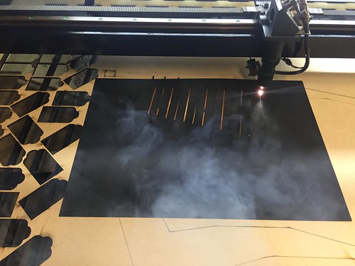 First cutouts of the final Chroma design.
 First cutouts of the final Chroma design.


 First build of laser cut bellows
 First build of laser cut bellows
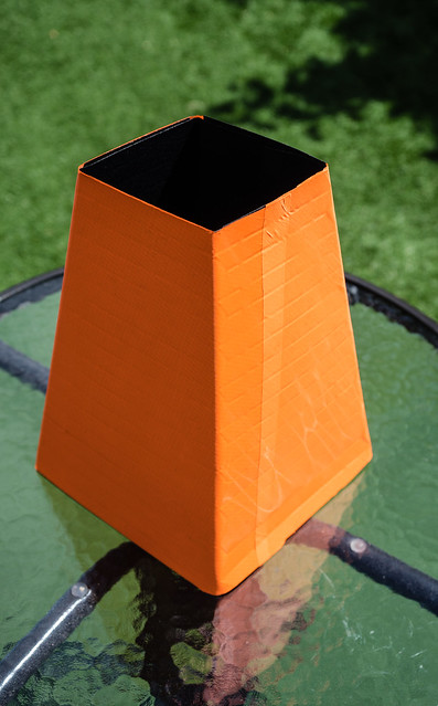 First build of laser cut bellows
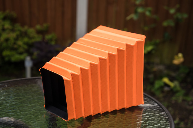 First build of laser cut bellows
 First build of laser cut bellows
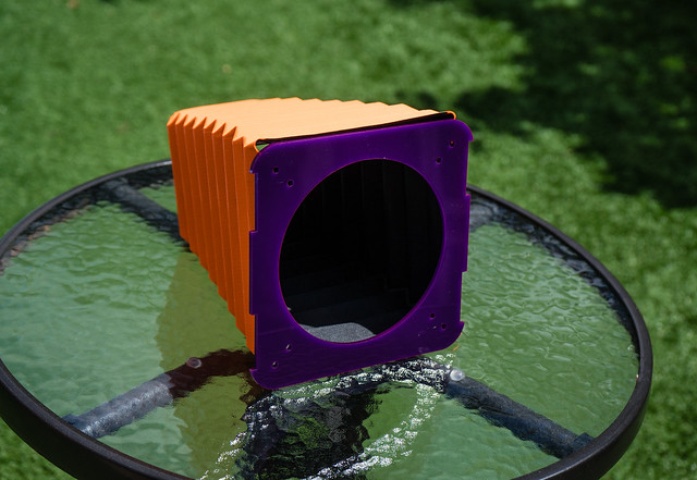 First build of laser cut bellows