Beginner An Idiots guide: DIY Water Drop Controller with Arduinos and stuff.

You are a master!....Thanks for the help and quick response...i'm so excited with this project and i think i'm gonna go for it with no doubts and turn my old existing project on this new one.
I have made one system with a light barrier and an Arduino Duemilinove but without solenoid and that wont let me to do waterdrops colision.
Thanks again Gareth
 
Hi Gareth,
A big thanks from me too (y) A bit of research had the pots sussed but I was struggling with the display a bit. I have bookmarked Paul McWhorter's guides and I'll be having look once the rest of the bits have arrived. I'm going to try and make mine on Veroboard so I can fit it into a plastic box that I have here already.

As an aside, I started to construct an adjustable sound, light or kinetic trigger for some high speed photography ages ago but never really got it working properly. I was thinking of trying it again with one of the other Nano boards that are on their way to me. That's something I wouldn't have considered doing with Arduino had I not seen your guide here so thank you once again :clap:
 
Hi Gareth. Sorry about the inconvenience but i still have one question : do you keep both buttons on the project?? ...the reset (on the reset pin of arduino) and the restart cycle button (on the pin 11 of arduino) ?
Thanks again.
 
You are a master!....Thanks for the help and quick response...i'm so excited with this project and i think i'm gonna go for it with no doubts and turn my old existing project on this new one.
I have made one system with a light barrier and an Arduino Duemilinove but without solenoid and that wont let me to do waterdrops colision.
Thanks again Gareth

You're welcome and the very best of luck Sérgio!(y)
Please let me know how your project progresses, I'd love to see some images.

Hi Gareth. Sorry about the inconvenience but i still have one question : do you keep both buttons on the project?? ...the reset (on the reset pin of arduino) and the restart cycle button (on the pin 11 of arduino) ?
Thanks again.

Yes, I will be keeping both buttons on my project, just for convenience.
I will be placing my project in a box that I'm making at the moment, so access to the reset button on the Arduino won't be possible, once it's sealed inside.
The other button (Arduino pin 11) is the start button, which is only necessary if you plan to have a similar program to the second, longer program that I wrote (CLICK HERE).

If you are planning to write a program similar to the first, simpler one (CLICK HERE), then there is no need for a start button, since the program will cycle automatically every 5 seconds - though of course you'll be tethered to the computer for the serial monitor interface.

The reason for the start button in the second version of the program, is that my controller will be independent from a computer, with no need for the serial monitor etc.
I thought it would be more convenient to have it to cause less wear and tear on the camera shutter!

You could delete the start button if you wished, and revert back to the 5 second cycle, but if you did, then you might find the reset button useful....just in case!

The reset button isn't really necessary in either version, I just have it in because I'm a bit paranoid I suppose!:giggle:
In fact there are some (experts) who believe it's not advised.
I personally don't understand why, since there is a reset button on the Arduino itself, and placing an extra one (wired to the reset pin), which works in exactly the same way hasn't caused me any problems at all.

Hope this helps.
Good luck!:)
 
Last edited:
Hi Gareth,
A big thanks from me too (y) A bit of research had the pots sussed but I was struggling with the display a bit. I have bookmarked Paul McWhorter's guides and I'll be having look once the rest of the bits have arrived. I'm going to try and make mine on Veroboard so I can fit it into a plastic box that I have here already.

As an aside, I started to construct an adjustable sound, light or kinetic trigger for some high speed photography ages ago but never really got it working properly. I was thinking of trying it again with one of the other Nano boards that are on their way to me. That's something I wouldn't have considered doing with Arduino had I not seen your guide here so thank you once again :clap:

You're most welcome Lee, glad that I could be even a tiny bit helpful.

My next project after this will be a sound trigger also, which I hope to use for some air gun pellet collision photography....with fruit etc.
I already have a working prototype, but I haven't tested it with my air gun yet....I'll need to build a rig in the garage to hold it safely, and build some sort of suitable pellet catcher etc.
And of course the car will have to live outside!:giggle:

I have made some preliminary calculations, which suggest that at a distance of 2 metres from the muzzle, the pellet flight time will be around 10 milliseconds.
I hope this is correct....shooting outside isn't an option round where I live!!

I've been amazed what these simple Arduinos can do, they really are a miniature marvel of technology.
Please keep me posted Lee, I'd be very interested in seeing some images you get from your project.

Cheers!:)
 
Hi.
Here is the first images of my project.
Am i going on the right way? This week will receive the solenoid and the electronic parts.
Thanks Gareth for the inspiration.
Untitled3.jpgUntitled2.jpgUntitled5.jpg
 
You're most welcome Lee, glad that I could be even a tiny bit helpful.

My next project after this will be a sound trigger also, which I hope to use for some air gun pellet collision photography....with fruit etc.
I already have a working prototype, but I haven't tested it with my air gun yet....I'll need to build a rig in the garage to hold it safely, and build some sort of suitable pellet catcher etc.
And of course the car will have to live outside!:giggle:

I have made some preliminary calculations, which suggest that at a distance of 2 metres from the muzzle, the pellet flight time will be around 10 milliseconds.
I hope this is correct....shooting outside isn't an option round where I live!!

I've been amazed what these simple Arduinos can do, they really are a miniature marvel of technology.
Please keep me posted Lee, I'd be very interested in seeing some images you get from your project.

Cheers!:)

I had a go a while back with a friends trigger (from HiViz.com). Your timing sounds like a good starting point. We were around 7 or 8m away and used 60mS or so depending how we wanted the subsequent photo to look but we varied it quite a lot - balloons bursting took a surprisingly long time! Plus hitting apples in pitch darkness was fun!

Some of the results are HERE. We used a .177 pistol with 7gr pellets.

I'll let you know how I get on (y)
 
@Picareto - looks like your project is going very well.
I like your method of stabilising the mariotte syphon bottle....I might 'borrow' that idea from you, if I may?! ;)
My bottles are just placed on the top piece, and are a little wobbly....in fact I've had a minor spillage due to this!

I had a go a while back with a friends trigger (from HiViz.com). Your timing sounds like a good starting point. We were around 7 or 8m away and used 60mS or so depending how we wanted the subsequent photo to look but we varied it quite a lot - balloons bursting took a surprisingly long time! Plus hitting apples in pitch darkness was fun!

Some of the results are HERE. We used a .177 pistol with 7gr pellets.

I'll let you know how I get on (y)

Great shots there Lee, can't wait to get mine built now....it's on hold for the moment however, but your photos have inspired me to get a move on!!
I'm using similar equipment - .177 cal with 6.9 gr pellets.
My trigger will activate the camera, like my drop controller, so I won't have to shoot stuff in the dark!!
As you say, sounds like fun, but I'm probably not as good a shot as you!:giggle:

I was hoping that the Arduino would allow for adjustments of less than a millisecond....say 10ths of a millisecond - allowing more fine adjustments rather than moving everything a few centimetres back and forth - but it seems this is much more difficult than I had anticipated....I might have to just make do with milliseconds, and hope there's enough scope for moving stuff around in my garage!!
 
@Picareto - looks like your project is going very well.
I like your method of stabilising the mariotte syphon bottle....I might 'borrow' that idea from you, if I may?! ;)
My bottles are just placed on the top piece, and are a little wobbly....in fact I've had a minor spillage due to this!

Please fell free to do it if you want :)
 
Great shots there Lee, can't wait to get mine built now....it's on hold for the moment however, but your photos have inspired me to get a move on!!
I'm using similar equipment - .177 cal with 6.9 gr pellets.
My trigger will activate the camera, like my drop controller, so I won't have to shoot stuff in the dark!!
As you say, sounds like fun, but I'm probably not as good a shot as you!:giggle:

I was hoping that the Arduino would allow for adjustments of less than a millisecond....say 10ths of a millisecond - allowing more fine adjustments rather than moving everything a few centimetres back and forth - but it seems this is much more difficult than I had anticipated....I might have to just make do with milliseconds, and hope there's enough scope for moving stuff around in my garage!!
Thanks Gareth.

I look forward to seeing the results. Everything that I have done with anything high speed has been with the camera shutter set on Bulb or a long exposure with no light. All the work is done by triggering the flash at lowest power to get the fastest "shutter speed" which is way faster then the shutter on my camera. I am very interested to hear how you get on triggering the camera.

PS - The Elegoo Nano's arrived today along with the solenoid valve :banana:
 
Last edited:
Hello

Just wondering if someone would be willing to sell me a working system?

I would love to say I have the time, patience and more importantly skills.. though I don’t though would like to explore a cost effective way of getting a system.

If there is some interest then we could move to a conversation about a ball park cost and what spec that would involve.
Thanks a lot
Vince
 
Hi Vince.:)

Firstly, thanks for your interest, it certainly is a fascinating style of photography, and well worth exploring.

Secondly, I can only speak for myself here, but my intention was to achieve my personal goal of building my own drop controller.
I appreciate and understand that time is precious for everyone, and while I sympathize that you may not have enough spare time to dedicate to a project like this, I nevertheless had no plan to sell my project.
Sorry if this seems a bit harsh Vince, hope you understand.

And finally, this thread isn't really the right place to discuss trades.
Enquiries should be placed in the wanted section of the trading forums HERE.
There has been trades for drop controllers in the past....one was a couple of months back.
Might be worth posting a wanted post there...see what happens.(y)
 
Morning Gareth

Fair point on the post going in the wanted section , hadn’t thought of that (y)

No it’s not harsh at all, no offence felt. Some people love the inventing stuff and I wondered if there were one who would want to add a twist producing a 2nd one to help fund more inventions. :)

Will pop something in a wanted ad
 
I had a go a while back with a friends trigger (from HiViz.com). Your timing sounds like a good starting point. We were around 7 or 8m away and used 60mS or so depending how we wanted the subsequent photo to look but we varied it quite a lot - balloons bursting took a surprisingly long time! Plus hitting apples in pitch darkness was fun!

Some of the results are HERE. We used a .177 pistol with 7gr pellets.

I'll let you know how I get on (y)

Good morning friends.
In the past i was playing with this Hiviz.com project....garage without light and 2 flashes+ remote trigger.Works like a charm.
I had to made some transformation on the old vivitar 283 flashes to lower the power of them....adding some resistors and a selector.With low power of light you will get more speed and the "freezing moment" is far so good.The results were not bad but i think my problem is the strong powerfull of the riffle! Because the speed of the pellets is too high...about 300m/s !!!
Soon i will post some photos.

(Sorry about my english! hope you understand)
 
Some photos that i did with that sound trigger project.
 

Attachments

  • balão dágua_web.jpg
    balão dágua_web.jpg
    411.7 KB · Views: 20
  • IMG_1909_web.jpg
    IMG_1909_web.jpg
    361.1 KB · Views: 21
  • ovo_web.jpg
    ovo_web.jpg
    185.4 KB · Views: 21
@Picareto - Sérgio, those images are incredible!! Fantastic work!!(y)

You're very inventive with your flashes....I don't think I would dare do anything like that....I just know I'd blow something up!:LOL:
300m/s you say?! Indeed, that's pretty quick! The air pistol I'm using is at around 170m/s, which considering it will be indoors is plenty fast enough.
I'm not sure what my rifles are rated at....they're quite old, but they're more powerful than the pistols for sure.
I might dig out one of my older pistols now that I think about it, they're less powerful than my Gamo....and it might be advantageous to have less muzzle velocity in a restricted space.

By the way Sérgio, your English is fine.(y)
 
They are cracking images @Picareto !

With regard to muzzle velocity, in the UK air pistols are (or should) be limited to 6 foot pounds maximum and rifles 12 foot pounds. For the same calibre and pellet weight, a rifle would typically have a higher muzzle velocity. An easy way to slow things down is to use a heavier pellet but remember that the pistol or rifle still has the same power!
 
Hi Gareth.
I am about to make all the electronic connections and now i have 2 doubts. There are two "9" pins (from lcd and breadboard) and two "10" pins!!!??? ....are they to connect together??
The other thing is about the restart button..... the sequence is pin11 to the button and the return is ground? ...no need some resistor?
Thanks in advance.
 
Oh!!!!....by taking a look at the code i see that the pin 9 is now the 7 and the pin 10 goes to 6 .... shame on me :(
 
Last edited:
All night long!!! ...IT WORKS !!!!! yeahhhhh!!!!
Because i dont have yet the solenoid i´m testing with a little 12vdc relay to ear the noise....beautiful indeed :)
Everything goes perfectly but there is some issues:
1- I was thinking that the start button was a momentary pushbutton to let the arduino makes one cycle of for example 2 or 3 drops .....but it only starts or stop the system :( what do you think about this possibility Gareth?
2-I notice that when i change the camera delay (CD pot.) the noise of the relay changes too!!!.....when it goes to zero the relay(future solenoid) goes much more quickly !!

Note: i´ve connected the start button like the button 1 on the photo below .....but at the pin 11 instead of pin 2 .

Many thank´s one more time.
 

Attachments

  • FY4DI4EIXQG34.jpg
    FY4DI4EIXQG34.jpg
    77.4 KB · Views: 46
Well....first impressions after testing with the solenoide valve that came a few hours ago:

It´s very dificult to adjust the "hot point"! and that´s because the flashes(in my system) wont stop firing and firing...its a mess of lights :)

Gareth i was thinking that maybe the best way to do the thing is to create a new sketch that allows cyles of 2 or 3 drops and do only a single camera/flash trigger everytime we press the momentary start button ....and of course if we keep the button always pressed than the system works continuously .What do you think about this Gareth??

Thanks in advance and sorry for my boring questions!!
 
Last edited:
Parabéns!(y)

Excellent work Sérgio!
Glad you have a working prototype.

They are good questions Sérgio, indeed the start button is supposed to start the sequence, but it should only do one cycle, and then wait until the button is pressed again to start another cycle.

This line of code is where the program waits.

C-like:
buttonSTATE=digitalRead(startBUTTON); 
    if(buttonSTATE==LOW) {                    //Wait for start button to be pressed before continuing

It shouldn't keep cycling, it should perform the solenoid and camera actions, then return to this inside the void loop and wait for the button to be pressed again.

I had some issues with the start button too, but because of my lack of electronics knowledge, I did some trial and error to get it to work.
I used a 1 KΩ resistor as a 'pull-up' resistor....I believe that's the right term!

I'm sure it won't matter which pins you connect, as long as you change the program accordingly.
It seems strange that your camera delay (CD) is changing the solenoid/relay too.
I know it seems obvious, but have you double checked the Arduino pins and the pot pins?
It could just be a simple oversight....I have made many myself!!:giggle:

Here is how I connected the start button circuit:

full


...and the diagram showing it in more detail:

full


Well....first impressions after testing with the solenoide valve that came a few hours ago:

It´s very dificult to adjust the "hot point"! and that´s because the flashes(in my system) wont stop firing and firing...its a mess of lights :)

Gareth i was thinking that maybe the best way to do the thing is to create a new sketch that allows cyles of 2 or 3 drops and do only a single camera/flash trigger everytime we press the momentary start button ....and of course if we keep the button always pressed than the system works continuously .What do you think about this Gareth??

Thanks in advance and sorry for my boring questions!!

Not boring at all Sérgio ....it's intriguing!

Again, I'm not sure why yours is cycling over and over. It should perform the cycle once and then wait for the start button to be pressed again.

Have you tried changing these lines of code?

C++:
int buttonSTATE=HIGH;              //set buttonSTATE variable to HIGH

...and the corresponding line:

C++:
buttonSTATE=digitalRead(startBUTTON); 
    if(buttonSTATE==LOW) {                    //Wait for start button to be pressed before continuing

I experimented changing the HIGH and LOW values to see what happened.
The way I wrote it in the sketch worked for me, but maybe it might be different for you.
Again, I'm no expert in Arduino or electronics, so I'm sorry if this isn't very helpful, I wish I could be more knowledgeable!

Good luck, let me know how you get on.(y)
 
Well i haven´t change nothing at all in the sketch.....don´t know what´s happening......i think my resistor´s connection on the start button it´s diferent from yours....i have conected the resistor to ground instead of 5v !!
 
Well i haven´t change nothing at all in the sketch.....don´t know what´s happening......i think my resistor´s connection on the start button it´s diferent from yours....i have conected the resistor to ground instead of 5v !!

You will definitely need to change your start button pin if you are using pin 2 on the Arduino.
My sketch shows pin 11 for the start button, so maybe that's why yours isn't working correctly.

Here's the line, it's near the top of the sketch...

C++:
const int startBUTTON = 11;        //assign pin 11 to startBUTTON

And maybe you could try changing the resistor to 5V instead of ground.

I'm sure you'll get it working Sérgio, Boa sorte! (y)
 
I´m already using pin 11 :) ....will try change the polarity of the conection like your diagram..... few minutes i will say something ;)
 
Thats it!! ....i´ve changed the connection and now it only does 1 cycle :) ...i´m thinking that changing the buttonSTATE in the sketch it would do the job also.
 
The CD pot only change the Drop Delay if we move it with the sytem working continuously....on cycle mode i did not notice any problem.
Gareth you are very kind to help with your tips....thanks a lot. Will do some more tests and show them here. :)
 
I´m already using pin 11 :) ....will try change the polarity of the conection like your diagram..... few minutes i will say something ;)

Ahh, ok fair enough.(y)

Thats it!! ....i´ve changed the connection and now it only does 1 cycle :) ...i´m thinking that changing the buttonSTATE in the sketch it would do the job also.

That's great Sérgio!
I'm glad you got it sorted!(y)
 
The CD pot only change the Drop Delay if we move it with the sytem working continuously....on cycle mode i did not notice any problem.
Gareth you are very kind to help with your tips....thanks a lot. Will do some more tests and show them here. :)

You're most welcome Sérgio.

I've just remembered something that might be important to the correct working of the LCD display.
Namely, the displayed delay values were not showing cleanly on the display for me....they were looking like random numbers.
The program worked fine, but it was difficult to see what the numbers were.
I researched and found that placing a 10 nF capacitor across the 5V (VDD) and ground(VSS) pins of the LCD worked, and now the display is clean and readable.

Perhaps you don't have this issue....I hope yours works well, but if you do, you could try putting in a capacitor of a similar value.

I will create a diagram and another info post in a short while.

Once again, well done for getting it to work, keep me posted!(y)
 
Testing and testing....it´s not easy to syncronizate everything.I´ve got so many "crowns" but double colisions not yet!..... could you tell me more about times and delays of the potentiometers? ....the delay time of the CD starts counting from the moment the Arduino sends the second signal to the valve, isn't it?
The bigger the size of the drop, the faster it gets to the water, is that so?


I've just remembered something that might be important to the correct working of the LCD display.
Namely, the displayed delay values were not showing cleanly on the display for me....they were looking like random numbers.
The program worked fine, but it was difficult to see what the numbers were.
I researched and found that placing a 10 nF capacitor across the 5V (VDD) and ground(VSS) pins of the LCD worked, and now the display is clean and readable.
The LCD works fine for me....seems like the scale above "100" shows the zero that was suppose to be at the left (like 070 for example) on the right and looks like 700....that´s not problematic.
 
Well for today it´s enough ..... I think my problem is even the CD delay! ..... Gareth the camera delay was designed by you for the camera trigger and not for the flashes .... they react faster than the camera trigger and I need to trigger them later, so the time scale is short and I need a longer delay ..... maybe a scale with double the time grrrrrrhhhhhh :)
 
Testing and testing....it´s not easy to syncronizate everything.I´ve got so many "crowns" but double colisions not yet!..... could you tell me more about times and delays of the potentiometers? ....the delay time of the CD starts counting from the moment the Arduino sends the second signal to the valve, isn't it?

Yes this is correct.
Experimenting with time delays can become very time consuming, but it's worth it.
I briefly talk about this in an earlier chapter - LINK HERE

The main things that will affect the timings are the viscosity of the liquid, and the distance between the tip of the drop nozzle and the surface of the liquid in the 'drop catch tray'.

I use Xanthum Gum (available from most health food shops or supermarkets) to thicken the water. A 1/4 of a teaspoon dissolved into 1 litre of water will yield a viscosity slightly thicker than milk, which is a good starting point.
I mix the xanthum gum with hot water (not boiling) in a blender, then allow to cool.
The result is slightly cloudy, but slightly thicker water. It's a good idea to strain the mixture too - this filters out any bits of undissolved xanthum gum.

The bigger the size of the drop, the faster it gets to the water, is that so?

Not necessarily. Because the drops are so tiny, they would likely fall at the same rate.
The drop size will affect the type of collision however.

Some sources that I have read, suggest that the first drop size isn't as important as the second drop size.
The aim of the first drop is to create a 'Worthington Jet'. - Here is Martyn Curreys page on capturing a worthington jet.
This is the rebounded column of water created when the drop hits the surface of the water.
The depth of the container you use for drops to fall into is quite important too - ideally the depth of the water should be at least 5 or 6 cm

There are ways to make the worthington jet taller....adding dish washing soap etc....but I have only just begun experimenting with this.

To achieve the 'crown' collision, it's probably best to start with a second drop that is smaller than the first one.

The height of the drop nozzle above the 'drop catch tray' is crucial for the timings.

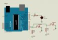
This next image was taken with the following timings: (all in milliseconds)

D1 - 30
D2 - 18
DD - 52
CD - 142


IMG_0587
by Gareth Bellamy, on Flickr

I used a wine glass as a drop catch tray, and the height between nozzle and the drop tray (wine glass) was ~ 40 cm

It's unlikely that you would be able to recreate the same exact same setup as me....liquid viscosity etc....so this is where the time is spent....in testing your personal system.
It can be tedious to cycle the drop controller, then take a photo, see nothing, cycle the controller again, take another photo etc.
I have pages and pages of notes I made whilst testing a huge number of time delays....most of them are worthless, but I did slowly begin to get a feel for what time settings worked and what didn't.

I do recommend making notes however, it can be very useful in the long run.
I would also recommend starting with just a single drop, and practising photographing the worthington jet.
Once you have a nice jet, you will have the basis of some good time delays.
And you need only concern yourself with adjusting one time delay value - namely the Camera Delay (CD) value.

Good luck Sérgio.(y)
 
Well for today it´s enough ..... I think my problem is even the CD delay! ..... Gareth the camera delay was designed by you for the camera trigger and not for the flashes .... they react faster than the camera trigger and I need to trigger them later, so the time scale is short and I need a longer delay ..... maybe a scale with double the time grrrrrrhhhhhh :)

That's a very good point! Sorry, I keep forgetting you are working with flashes directly!:sorry:
Of course my timings are going to be ever so slightly different due to the camera delay.
It would only be a matter of making some tiny changes....of the order of a millisecond, but I'm sure you'll get results very soon.

A good nights sleep will fix it for you!!:giggle:
 
Sleep does not seem to arrive.... :)
The delay comand it suppose to be máx 1,023 s . Alternatively we could use the time unit command of milisec instead of delay ... there we had the freedom to choose the maximum and minimum corresponding time of the potentiometers :) hope i am not saying mistakes :) :)
But i am trying this modification in the sketch to double the delay time of the flashes :

camDEL=analogRead(potFOUR) * 2; //read analogue value from potentiometer 4 (analogue value x2)

....tomorrow i will test it. After purchase the Xanthum Gum :) :)
I wonder if that product will prevent multiple smaller droplets.

Thanks Gareth
 
Last edited:
I am still quite inexperienced in Arduino programming, so please forgive me if I don't understand!

I thought the delay command is already in milliseconds...
an example line:

delay(1000);

this would delay for 1000 milliseconds or 1 second.

I'm afraid I'm not familiar with the millisec command. How is it different from the delay command?

With regard to the pots, all I have learned is from Paul McWhorters guides on toptechboy.com (lesson 10 - link)
He explained that the pots act like variable voltage dividers, and the Arduino reads the analogue voltages between 0V and 5V
Arduino then outputs a digital value between 0 and 1023

So if you put the pot at half way for example, then that would be an analogue voltage of 2.5V
Arduino will output a digital value of 1023/2 = 511.5 or 511 since we are working with integers (int)
I then use that value as a delay in milliseconds....511 milliseconds

Of course the maximum value of 1023 milliseconds is too large for our drop controllers, so I added a division to increase the resolution.
That's what is happening in this line:

C++:
camDELval=camDEL/(5.);                    //divide dropFOUR value from potFOUR by 5 to increase accuracy

So for our half way value of 511, the actual time delay would be 511/5 = 102 milliseconds which is more manageable and means the pot can be more accurately adjusted.

I'm not sure if this is the right way to interpret it....I am still a beginner with Arduino and I have a lot to learn!!:giggle:
I hope it makes sense Sérgio :)

I think that if you double the time delay, you would have time delays that are too big, is that right?
Again, it may just be me being inexperienced, but I hope your testing works out....please keep me posted, I would be very curious to know how it works.

....tomorrow i will test it. After purchase the Xanthum Gum :) :)
I wonder if that product will prevent multiple smaller droplets.

Yes it will. Normal water is too runny and splashy! :giggle:
Adding xantham gum will make it much more controllable.

Good luck Sérgio (y)
 
Hi once again.
With regard to the pots, all I have learned is from Paul McWhorters guides on toptechboy.com (lesson 10 - link)
He explained that the pots act like variable voltage dividers, and the Arduino reads the analogue voltages between 0V and 5V
Arduino then outputs a digital value between 0 and 1023

So if you put the pot at half way for example, then that would be an analogue voltage of 2.5V
Arduino will output a digital value of 1023/2 = 511.5 or 511 since we are working with integers (int)
I then use that value as a delay in milliseconds....511 milliseconds
Gareth what you said is totally correct in my opinion,even if my arduino skills are very basic too....
delay(1000);

this would delay for 1000 milliseconds or 1 second.
When we use the command "delay" the máx. value of the potentiometer is 1023 that refers to 1023ms.For other scales of time you should use the map() function to map this to the range of time that you need. For example, if you want a delay between 0 and 3 seconds, then use map function to change the range (0,1023) to (0,3000) milliseconds. :) (
I read this I do not know where :) )

The first results are coming. :)
I´ve changed again the sketch as i need more delay to trigger the flash :
camDELval=camDEL/(3.); //divide dropFOUR value from potFOUR by 3 to increase accuracy
Maybe i´m loosing some accuracy but it worked!!.....
There is some issues too about the lcd values!....sometimes i do not know if the displayed value is 830 or 83. It happens to have 830 for example and if I disconnect the power to the Arduino and reconnect it now displays 83 !!! is that the reason for it because it only show 3 digits? I think there is some confusion with these numbers.
Other thing is that i'm trying to get a tall, beautiful reflux of the first drop ... still unsuccessful :(

Leave a non edited file to your appreciation.
Tanks for all.
 

Attachments

  • Untitled.jpg
    Untitled.jpg
    27.7 KB · Views: 23
Last edited:
The values for that drop colision where: D1-1000 D2-750 DD-800 CD-354 too high isn´t it?? The distance from the end of the nozzle(where the drop falls) to the water surface is my case is 42,5cm.
 
Hi once again.

Gareth what you said is totally correct in my opinion,even if my arduino skills are very basic too....

When we use the command "delay" the máx. value of the potentiometer is 1023 that refers to 1023ms.For other scales of time you should use the map() function to map this to the range of time that you need. For example, if you want a delay between 0 and 3 seconds, then use map function to change the range (0,1023) to (0,3000) milliseconds. :) (
I read this I do not know where :) )

Thanks Sérgio - I will need to do some more research, but I think I understand.(y)

The first results are coming. :)
I´ve changed again the sketch as i need more delay to trigger the flash :
Maybe i´m loosing some accuracy but it worked!!.....

Brilliant! I've looked at your unedited image and it's a great result....it's a really nice collision, well done Sérgio!

There is some issues too about the lcd values!....sometimes i do not know if the displayed value is 830 or 83. It happens to have 830 for example and if I disconnect the power to the Arduino and reconnect it now displays 83 !!! is that the reason for it because it only show 3 digits? I think there is some confusion with these numbers.

This is the same problem I had - see post #69 - LINK
I solved this problem by adding a 10 nF capacitor across the GND (VSS) and the 5V (VDD) of the LCD screen.
It worked very well, and now the numbers are very easy to read.

I have made a separate post (with photos/diagrams) on this subject, you can find it by CLICKING HERE

Other thing is that i'm trying to get a tall, beautiful reflux of the first drop ... still unsuccessful :(

This can be a tricky, time consuming process, with many variations on what additives to use.
Here is a video which I found somewhat useful:

View: https://www.youtube.com/watch?v=oS_QRhVBOck
 
Last edited:
The values for that drop colision where: D1-1000 D2-750 DD-800 CD-354 too high isn´t it?? The distance from the end of the nozzle(where the drop falls) to the water surface is my case is 42,5cm.

Those numbers do look a bit high, yes.
But if you took the collision image that you showed above, then you must have made the right adjustments in the sketch.
Maybe it's just printing the wrong values to the LCD, but the time delays in the sketch are correct

Maybe you need to double check the values that are being printed to the LCD to make sure they are the actual time delays.

Even though you are firing your flashes, and I am firing my camera, I would think that the time delays would be roughly similar because our nozzle heights are similar.
They would certainly be within a few milliseconds of each other.
 
LCD display problems.

Upon connecting up the LCD and being thrilled that it worked, I saw that I still had a problem.
The digits on the LCD seemed to have 'ghost' figures still displayed after adjusting the values.
The program worked well, and the time delays were accurate, but I couldn't clearly see what the time delays were.

Here is a photo:

full


The time delays were actually:

D1 - 00
D2 - 51
DD - 41
CD - 142

After reasearching, I found that a solution was to add a small capacitor across the GND (VSS) and 5V (VSS) of the LCD.

Another photo of the capacitor in place:

full


The capacitor that I used was a 10 nF ceramic disc capacitor, which because they have no polarity, can be connected either way round.

Here is a diagram showing how it's connected:

full


Now the LCD display shows all the time delays clearly, with no 'ghost' numbers....a success!
 
Last edited:
Back
Top