Another idiots guide - DIY flash trigger for high speed photography.

Messages
2,031
Name
Lee
Edit My Images
No
Hello All,

Following on from stumbling on the thread by @GarethB HERE of how to build a a water drop controller, I maybe sort of got a bit interested (read addicted) in building some more gadgets based around an Arduino Nano clone. My thanks go to Gareth for re-igniting my interest in electronics (y)

I have based this tutorial format shamelessly on the Waterdrop one as I found that very easy to follow.

The Nano clones that I bought for the water drop project came in a pack of three (LINK). The second one got used as a timer for an aquarium light as the original one stopped working (I'm happy to share the information for that via PM if anyone is interested). Thoughts then focused on the third Nano...

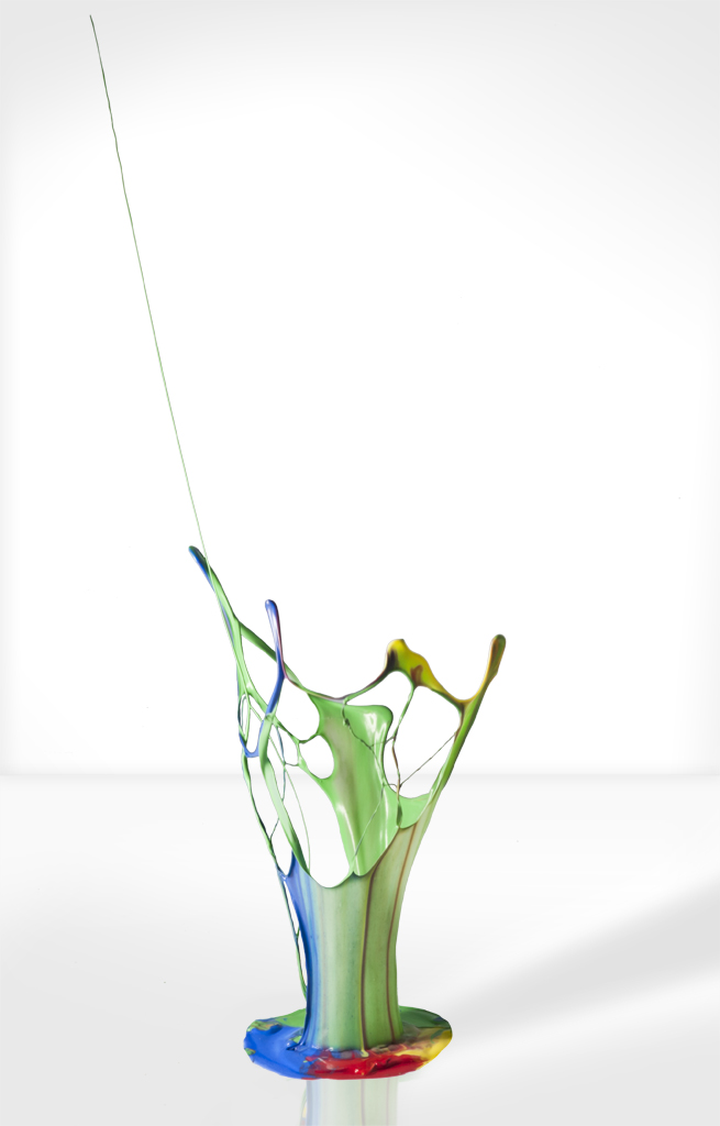
I really like creative photography and a chance chat with a friend revealed that he had a HiViz multi-trigger. We met up and had great fun shooting some high speed photos using off camera flash to effectively illuminate the subject for a very short time - in the region of 1/20,000 second. Much faster than the highest shutter speed on my camera (1/4000 second). The results were something like this...


Apple shot by Lee Francis, on Flickr

I then got to thinking that I could build a similar trigger system for a lot less money. So, without further ado, below is a tutorial to build an Arduino piezo sensor flash trigger...

I have built my DIY project on Veroboard or stripboard (LINK) but I will run through building it on breadboard (LINK) to make it easier for those that would rather do a minimal amount of soldering.

Useful equipment (but not all of it essential)...
Simple multi-meter for testing DC voltage and resistance etc.
Soldering iron and solder;
A set of Helping hands (those arm things with croc clips on the ends for holding small stuff);
A PC or iMac to run the Arduino software;
White tape and a pen for labelling wires etc.

Items that I needed to get...
Arduino Nano (I got myself a three pack) LINK
A piezo ceramic sensor (listens for the noise / impact) - LINK
A 4N35 optoisolator (used to electrically separate the flash from the circuit - LINK
A 220 ohm resistor to drive the 4N35 - See note 1 below...
A 1 Meg ohm resistor for the piezo sensor - See note 1 below...
A 4.7 volt Zener diode (to protect the Nano / Uno from potental voltage spikes from the piezo sensor) - LINK
A 330 kilo ohm resistor for the start switch - See note 1 below...
Two 470 ohm resistors for the power and ready LEDs - See note 1 below... (Optional)
Breadboard jumper wire kit (if using breadboard) - LINK. Or, if using vero board / strip board, get a hank of hook up wire - LINK
A start button (momentary switch - to tell the Nano to listen to the piezo sensor) - LINK
A power switch - LINK
Two 10 Kilo ohm adjustable resistors (called potentiometers. Used to adjust the sensitivity and delay time) - LINK
Connectors / leads to connect to your flash and to connect the piezo sensor to the Nano - detail to follow...

Note 1 - Resistors can be purchased as a muti pack of most of the usual types - LINK

Other items required will be an appropriate lead to control your off camera flash / speed light. I am a Nikon user and I use a Yongnuo 560III flash with a hot shoe adapter similar to this (LINK).

I'll go into the construction detail in subsequent posts. Below are a few shots of my flash trigger and sensor. This is a slightly earlier version as, like all of my projects, it has evolved as I built it! The current version is Mk3.

View media item 106837
View media item 106835
View media item 106836
 
Last edited:
As Arduino is all 'open source', there is loads of information on the internet for countless projects. If you type a project thought into your favourite search engine, almost certainly someone would have done at least something similar before. This project takes parts from at least three such projects that I found.

I use TinkerCAD to design the initial circuit. I find it easy to use and it is perfect for seeing if most projects will work as you can upload your own code and simulate the project without having to build anything. I say most as not all components are available to use / simulate. For instance, this project uses a piezo as an input and TinkerCAD can only seem to deal with it being an output (buzzer).

The project initially didn't have a start button or a sensitivity control. The lack of a start button meant that the flash would keep going off whilst I moved the piezo sensor around to re-set up the shot etc. The lack of sensitivity control was a bit of an oversight as I was excited to see if my project worked! The Mk2 version added these two features. Mk3 came about as I couldn't remember if I had pressed the start button a few times so I added a Power LED and a Ready LED to the Mk3 version.

Here is the design for the Mk3 version...
View media item 106969
As I mentioned, Arduino is 'Open source' so having an Arduino clone of a Nano is not a problem because it can be programmed by the Arduino software which is available free from the Arduino website LINK. It's worth mentioning though that some of the Arduino Uno and Nano clones may need a couple of minor setting changes before the the software and the Uno / Nano clone 'talk' to each other. With the Elegoo Nano clone linked above, I had to select the Arduino Nano board with old bootloader in the Arduino software as it wouldn't 'talk' with the new one. I am led to believe that this is because the Elegoo Nano has an older communication chip on it.

View media item 106955
The code is quite straightforward. I am very much a beginner though and welcome any comments to tidy it up. As the code has evolved, I may have inadvertently left in some lines that are no longer required. Especially when setting up the variables and pin modes etc.

C++:
const int LED_READY = 12;                                 // assign pin 12 to LED READY
const int FLASH_PIN = 3;                                  // assign pin 3 to FLASH TRIGGER
const int DELAY_PIN = A0;                                 // assign pin A0 to DELAY POT
const int SOUND_PIN = A2;                                 // assign pin A2 to TRIGGER INPU
const int THRESHOLD_PIN = A3;                             // assign pin A3 to THRESHOLD POT
const int BUTTON_PIN = 2;                                 // assign pin 2 to start BUTTON
const int potONE = A0;                                    // assign pin A0 to potentiometer 1 - Delay
const int potTWO = A3;                                    // assign pin A0 to potentiometer 2 - Sensitivity
int camDEL;                                               // declare camDEL variable
int camDELval;                                            // declare camDELval variable
int BUTTON_STATE;                                         // declare BUTTON_STATE variable
int THRESHOLD;                                            // declare THRESHOLD variable
int THRESHOLDval;                                         // declare THRESHOLDval variable
int pMin = 0;                                             // the lowest value that comes out of the potentiometer
int pMax = 1023;                                          // the highest value that comes out of the potentiometer.

void setup()
{
  pinMode(BUTTON_PIN, INPUT);                             // make button press pin input
  pinMode(FLASH_PIN, OUTPUT);                             // make flash trigger pin output
  digitalWrite(FLASH_PIN, LOW);                           // keep flash trigger pin low
  pinMode(DELAY_PIN, INPUT);                              // make pot pin an input
  pinMode(LED_READY, OUTPUT);                             // make ready LED pin output
  digitalWrite(LED_READY, LOW);                           // ready LED off
}

volatile int v1 = 0;
volatile int v2 = 0;

void buttonWait(int buttonPin){
  int BUTTON_STATE = 0;
  while(1){                                               // wait for ready button to be pressed routine
    BUTTON_STATE = digitalRead(BUTTON_PIN);
    if (BUTTON_STATE == HIGH) {
      return;
    }
  }
}

void loop()
{
      buttonWait(2);                                      // check if button is pressed, only continue when pressed.

      digitalWrite(LED_READY, HIGH);                      // light ready LED
      THRESHOLD=analogRead(potTWO);                       // read analogue value from potentiometer 2 (SENSITIVITY)
      THRESHOLDval = map(THRESHOLD, pMin, pMax, 2, 500);  // map value from potTWO to be between 2 and 500 to increase accuracy
      Serial.println(THRESHOLDval);
    
      while (abs(v1 - v2) < THRESHOLDval) {               // if difference between two analog read exceeds threshold, then exit loop and trigger flash
      v1 = analogRead(SOUND_PIN);                         // start analog read
      v2 = analogRead(SOUND_PIN);     }                   // acquire again
    
      camDEL=analogRead(potONE);                          // read analogue value from potentiometer 1 (DELAY)
      camDELval=camDEL/(5.);                              // divide value from potONE by 5 to increase accuracy
      delay(camDELval);                                   // delay for time value camDELval - delay between sensor activation and flash activation

      digitalWrite(FLASH_PIN, HIGH);                      // trigger flash
      delay(10);                                          // keep flash trigger high for 10ms
      digitalWrite(FLASH_PIN, LOW);                       // done triggering, reset back 

      v1 = v2;                                            // reset piezo sensor values       
      digitalWrite(LED_READY, LOW);                       // turn off ready LED
      BUTTON_STATE=LOW;                                   // reset Ready button
      delay(500);                                         // wait 500mS
}
 
Last edited:
That's great work Lee!:clap:
And thanks for the shout out!!(y)

This is just the kick in the pants that I need to reignite my own projects, so a big thank you to you too Lee!(y)

I love the images you've produced so far - really excellent work indeed....I'm so envious!!:D

Your mk3 version looks really great in that slick looking box, I'm very impressed.

I thought I would mention the bootloader however.
A few weeks ago, I got brave and decided to burn the (Elegoo) UNO bootloader onto all my (Elegoo) NANO boards, since I have a few of each, so that I wouldn't need to worry about changing any settings ever again.
It worked like a charm, and now all my NANOs think they are UNOs, and I no longer need to fiddle about with settings anymore.
I don't think it makes any difference to the performance of the boards, I think it's just a convenience thing, but worth doing if you have UNOs and NANOs....if not, then I don't think it would matter.

I watched this YouTube guide on how to do it:

View: https://www.youtube.com/watch?v=yAQOu1RoxHM


Also, sorry to get all nit-picky....but I think there might be a typo in the line:

while (abs(v1 - v2) &amp;lt; THRESHOLDval) { // if difference between two analog read exceeds threshold, then exit loop and trigger flash

Is the bold bit supposed to read && - to denote logical 'AND'?

Best of luck to you Lee on your projects....say, d'you think if our 'idiots' guides were smashed together it would make us half 'idiots' or double 'idiots'?!:D
 
Hi Gareth,

Thank you for your kind words and the information regarding the Bootloader. I'll take a look into that.

Thanks for spotting the issue with the line of code. It's fine when I look at it in the Arduino software so it must be a funny forum / HTML formatting thing. I have updated the post to put the programming in a C++ code box rather than just have it in the message body.

Thank you. :LOL: I'd have to go with half idiots at least although I still have so much to learn with these amazing little Arduinos :D

EDIT - I've just noticed that I didn't add a link to TinkerCAD. I find it a nice and simple online tool - LINK
 
Last edited:
On to the sensor part.
It is a Piezo electric transducer. It can either have a pressure applied to it (impact or sound waves) and produce a voltage (a sensor as used here) or a voltage can be applied to it via a suitable circuit and it can emit a sound - think of one of those annoying birthday cards that plays a tune as it is opened.

I mounted my sensor in-between two small pieces of plastic that I happened to have lying around with a thin sheet of foam in the middle.

View media item 106964
I used a central dot of glue on one side and a thin circle on the other in an attempt to maximise how much the sensor flexed (and therefore generate a bigger signal). In practice, I didn't really need to do this as it was very sensitive for my use. I expect that the sensor could be simply stuck to a surface which is going to experience the impact and it would work although I haven't tried that.

View media item 106965View media item 106966
The sensor came supplied with short wires already attached. I extended these and wired a phono plug on the end. To minimise the amount of soldering, a cheap phono extension lead or similar could be used with the socket end cut off - LINK Extension leads like these are usually made up from 'figure 8' cable and the wires can typically be stripped apart form each other so you haven't got unused plugs getting in the way.

As a rule of thumb, I always connect the positive (red) wire to the centre or tip of a connector. If possible, I use different connectors for each input or output so that I can't mistakenly get plugs mixed up.

Flash connection part.
I used an ebay hotshoe adapter that I already had which triggers the flash with a suitable lead. LINK It has a standard camera screw thread in the bottom so it could be mounted onto a tripod etc. I connected that back to the controller with a cheap mono male to male 3.5mm lead - LINK

View media item 106970
 
Last edited:
Amazing work! I love all the stuff you can do with arduinos. I currently try my hand on a basil irrigation system for my kitchen window sill haha.

A long time ago, I wanted to try out high-speed photography like this, but at a very low budget. A friend and me built a setup (copied from some forum), where the sensor was basically two sheets of aluminium kitchen foil, connected to cables with sellotape. The 2 cables, when connected (i.e. the sheets touch), would trigger the flash by just connecting the trigger pins on the bottom of the flash (in my case it was the big one in the middle on a canon 430ex). Activation was by fragments of the apple or whatever touching one of the sheets. It looked more or less like this (see below). Sadly I can't find the pictures at the moment, it definitely kind of worked :LOL: but for anything more serious it was rubbish of course.

IMG_0013.jpg
 
@Cambtrader - That looks like a great fun way to do it. Often the simplest ways work. Thank you for sharing that. I'll have to give that a try and see I can capture :D If you do happen to find any of the photos, please post them (y)

When you mentioned about connecting the wires to the flash that reminded me that when I first connected my flash to the Mk3 circuit shown in my second post, it initially didn't work. I swapped the wires around and it worked fine. I think it is due to the way that the 4N35 chip switches it's output. It's essentially a photo-transistor being used as a switch. If my old electronics knowledge serves me well, it will only conduct in one direction.
 
Hi Lee,
Been following you on Gareth's thread and now here.
Thinking of building something.
Let's see ;)

Regards
Tony
 
Hi Tony,

I saw your post in Gareth's thread. I look forward to seeing to hearing your progress and seeing your photos :)

My project has taken a bit of a back seat at the moment due to life generally getting in the way but I have a long and relatively clear weekend coming up so watch this space :D

Cheers,
Lee
 
It's been a while but I have finally got around to conducting some tests.

I set up a wine glass of water on the floor and lined up my projectile - a grape. I set the camera up and turned off the lights. The first few attempts were foiled by the fact that I couldn't see where I was dropping the grape but I got around that by having a dim light reflecting from the ceiling so I could see what was going on but it wasn't too bright such that it ruined the shot.

I experimented with the flash delay and sensitivity to get the right shot. The sensitivity proved tricky. It seems to be a bit too coarse and non linear in operation. Initially, after the first few goes, the drops off the wet grape were triggering the flash but turning down the sensitivity a bit meant that it didn't trigger at all. A little more experimentation with the code is required here I think...

Anyway, enough of my rambling. Here is a Triptych of the more successful shots that I took...

[url=https://flic.kr/p/2hbWsXt]
Splash art by Lee Francis, on Flickr[/URL]
 
I finally used the project in anger! It was for my 52 project (here). The theme was a song or title. Red red wine came into my head for some reason and I have always wanted to take a photo of a wine glass or wine glasses at an angle but with the camera on the same angle so the glass is upright but the contents is at an angle if that makes sense.

This idea went one stage further with the thought that I could get the 'wine' splashing out of the glass somehow. I had a drawer slide out of an old filing cabinet and screwed it to two bits of wood. I clamped that in a Workmate at an angle so that I could pull back and release the slide. Once I had got the angle right (not too fast and not too slow), I set the camera up at the same angle. I put two small panel pins in front of the glass and a small cable clip on the rear. The sensor was simply sat on the workmate to the right of the glass and covered with a couple of sheets of kitchen room for the inevitable mess! Behind the glass was a sheet of white foam as a flash diffuser and the flash (Yongnuo 560 III) was behind that.

The first attempt with the set up is below:
Red Red Wine-2.jpg

It took a few goes to get the delay and exposure correct to get the shot that I was after. It took me by surprise how long it took the liquid to get out of the glass. The final edited shot is below. A high key look made the gradient lines in the foam disappear. Quite possibly the trickiest part was minimising reflections on the glass. Strategically placed cardboard sheets sorted most of that out though.

Red Red Wine.jpg

Next time I intend to sacrifice some fruit like the shot in my opening post!
 
Hi Leebert, Thank you so much for this post, just what I needed. Second, hope you're still following this thread as I have a question. I built your device as per the code provided and it works a treat. Especially when using springs to fire a stick into the underside of an acrylic plate that has some paint drops applied (see photo).
My Problem is that I'm now trying that paint drops on a balloon covered speaker and for some reason the flash fires as soon as the first sound waves come from the speaker. The delay pot isn't doing anything. Did you make any revisions to your code, I think you had similar issue with grapes shots?
I too like flinging liquids about, I was going to add a link but as a new member I'm not allowed :(

Hi Eugene,
Well done for making the trigger and that is an epic image. It's not a method that I had thought of. Excellent stuff. :banana::clap::clap:
I look forward to more of your images (y):cool:

As for the code, I can't remember if I did anything but below is the latest version that I have.

I'll have a look at the actual circuit to see if I changed anything there. The delay is quite subtle but there is definitely a noticeable change between minimum and maximum. Try the Delay at both extremes of travel whilst manually setting the flash trigger off (by tapping it for example).

Let us know how you get on. I'll let you know if there were any more changes that I can find.

Code:
const int FLASH_PIN = 3;           //assign pin 3 to FLASH TRIGGER
const int DELAY_PIN = A0;          //assign pin A0 to DELAY POT
const int SOUND_PIN = A2;          //assign pin A2 to TRIGGER INPU
const int THRESHOLD_PIN = A3;      //assign pin A3 to THRESHOLD POT
const int BUTTON_PIN = 2;          //assign pin 2 to start BUTTON
const int potONE = A0;             //assign pin A0 to potentiometer 1 - Delay
const int potTWO = A3;             //assign pin A0 to potentiometer 2 - Threshold
int camDEL;                        //declare camDEL variable
int camDELval;                     //declare camDELval variable
int BUTTON_STATE;                  //declare BUTTON_STATE variable
int THRESHOLD;                     //declare THRESHOLD variable
int THRESHOLDval;                  //declare THRESHOLDval variable
int TIMEOUT=500;                   //500 milliseconds
int pMin = 0;  //the lowest value that comes out of the potentiometer
int pMax = 1023; //the highest value that comes out of the potentiometer.

void setup()
{

  Serial.begin(115200);
 
  pinMode(BUTTON_PIN, INPUT);      // make button press pin input
  pinMode(FLASH_PIN, OUTPUT);      // make flash trigger pin output
  digitalWrite(FLASH_PIN, LOW);    // keep flash trigger pin low
  pinMode(DELAY_PIN, INPUT);       // make pot pin an input
}

volatile int v1 = 0;
volatile int v2 = 0;

void buttonWait(int buttonPin){
  int BUTTON_STATE = 0;
  while(1){
    BUTTON_STATE = digitalRead(BUTTON_PIN);
    if (BUTTON_STATE == HIGH) {
      return;
    }
  }
}

void loop()
{
      buttonWait(2);                                      // check if button is pressed, only continue when pressed.

      THRESHOLD=analogRead(potTWO);                       //read analogue value from potentiometer 2
      THRESHOLDval = map(THRESHOLD, pMin, pMax, 2, 500);  //map value from potTWO to be between 2 and 500 to increase accuracy
      Serial.println(THRESHOLDval);
      
      while (abs(v1 - v2) < THRESHOLDval) {               // if difference between two analog read exceeds threshhold, then exit loop and trigger flash
      v1 = analogRead(SOUND_PIN);                         // start analog read
      v2 = analogRead(SOUND_PIN);     }                   // acquire again
      
      camDEL=analogRead(potONE);                          //read analogue value from potentiometer 1
      camDELval=camDEL/(5.);                              //divide value from potONE by 5 to increase accuracy
      delay(camDELval);                                   //delay for time value camDELval - delay between second drop and camera activation

      digitalWrite(FLASH_PIN, HIGH);                      // trigger flash
      delay(10);                                          // keep flash trigger high for 10ms
      digitalWrite(FLASH_PIN, LOW);                       // done triggering, reset back   

      v1 = v2;
 
      delay(500);
      BUTTON_STATE=LOW;
      
}
 
Hi Lee, Thanks for getting back to me. So far I've tested my pots for function and they both work fine. I think I may have been able to achieve a very small delay setting pot to max (I'm using 1K ohm ten-turn pots). I find ten-turn pots give more fine tuning.
Strange thing is I seam to remember having more control with the same set up on my other rig (stick up the bottom rig).
Anyway, I'm having to pause for a bit now as Mrs S reckons that as a now redundant grandparent I've got plenty of time to do all those jobs I've been too busy for in the past. Thanks again. Eugene
 
Hi Eugene,
Good that it all works. With 10 turn pots, you could always 'comment out' the line below by starting the line with two forward slashes.

So...
camDELval=camDEL/(5.); //divide value from potONE by 5 to increase accuracy

becomes...

//camDELval=camDEL/(5.); //divide value from potONE by 5 to increase accuracy

Have fun and please post your images :)
 
Hi Lee, The comment out suggested caused the green ready light to stop functioning, as did the latest version of the code posted the other day. I decided to reprogram with original code and all works fine again. I noticed that I could in fact control delay by looking at the position of the balloon membrane in the shot even though there appeared to be no apparent delay. The problem is that this shot still has so many variables to consider ie:
  • The consistency of the paint
  • The size of the paint spot
  • The amount of the delay (also dependent on the consistency of the paint)
  • The frequency of the sound that triggers the trigger
  • The volume etc etc.
Still I've made a brave start (though not that impressive when you look at what's out there).
Always remembering it's achieved with stuff I've made myself with the help of somebody else's code :)
Not there yet but on the right track?

Hi Eugene,

I'm not sure why it would affect the LED but if you have working now that's all that matters.

The photos you have posted are simply excellent! They are so very creative - you're definitely on the right track :clap: What sort of paint do you use? I might try something similar during this extended lockdown period that we find ourselves in.
 
Hi Lee, I'm using tubes of acrylic paint which react best when watered down (2/3 paint 1/3 water). Tried to add little drops to balloon stretched over speaker (see previous shots). I't all very hit and miss and is very dependent on frequency of sound. I started with opening chords of 20th Century Boy (v/heavy base) without success. Then I read about onlinetonegenerator.com where you can create a sound file to save as an mp3. My best shots work at 50hz square wave.
My speaker is a puny 5W 4 Ohm so think I need a bigger speaker/amp set up. Here's latest shot enabled by your trigger.
Cheers,
Eugene

Hi Eugene, Thanks for sharing and explaining how you have been taking these amazing shots. They are really excellent!
The last time I used a speaker I was playing with non-Newtonian fluids (made with custard powder). I downloaded a tone generator app on my phone and used that via an old set of PC speakers. There were some interesting (and messy) results :) If I find a photo, I'll post it.
 
Back
Top