UAV, Drone, Hexacopter build. - Updated 23-June-15 Flight Test.

mho

Messages
3,134
Name
Mark
Edit My Images
No
Hi,

I have been looking at UAV or Drones or Multicopters for a while now, and after what has felt like an age doing research etc, I am now ready to start the build,
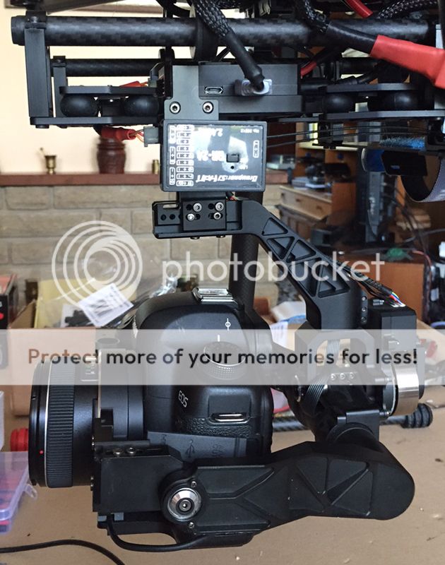
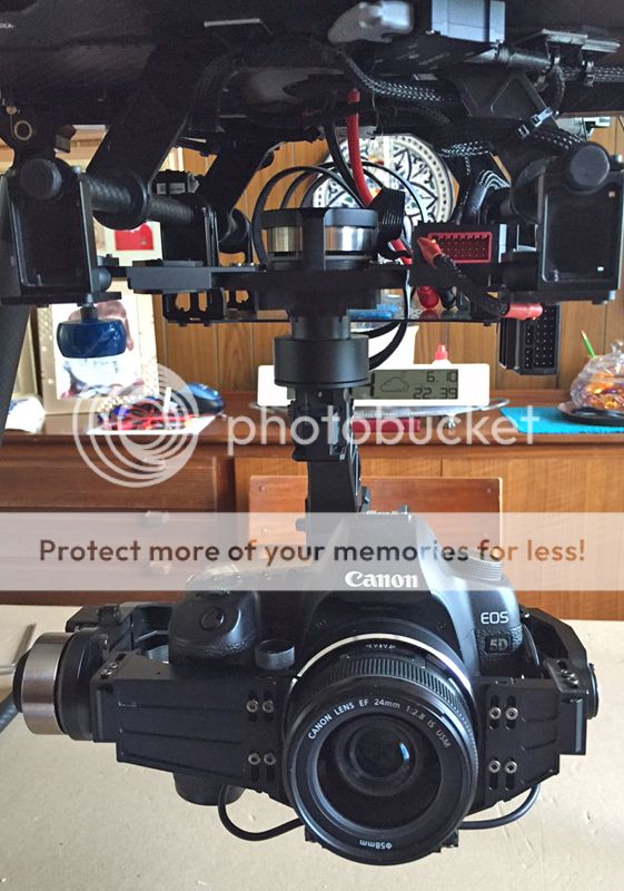
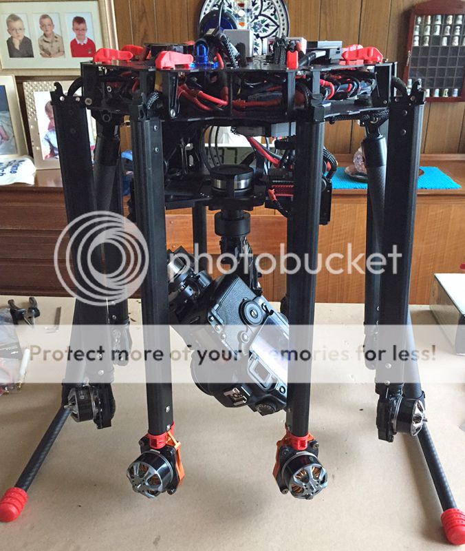
I have decided upon a Hexacopter (6 motors), this gives me a great power to weight ratio and stability, and has to be capable of carrying large battery, gimbal and a Canon 5D2 with 24mm f2.8 IS USM lens, Im not building it primerally for video or I would have chosen a smaller frame and either a go pro or Black magic camera, I want to use it for photography as well.

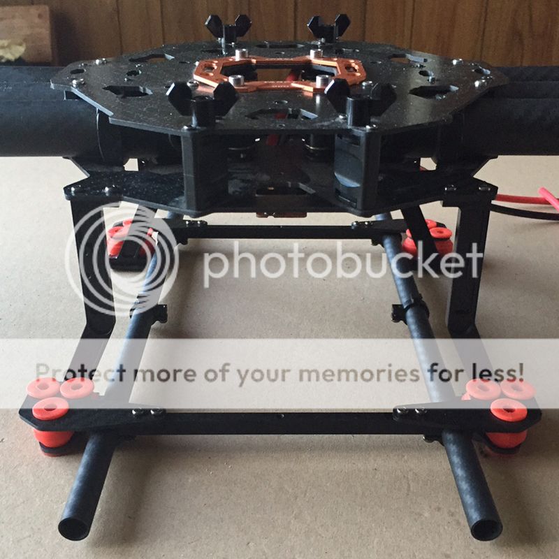
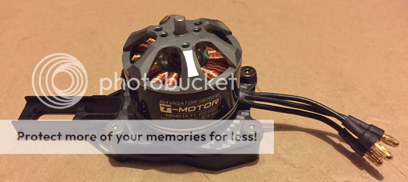
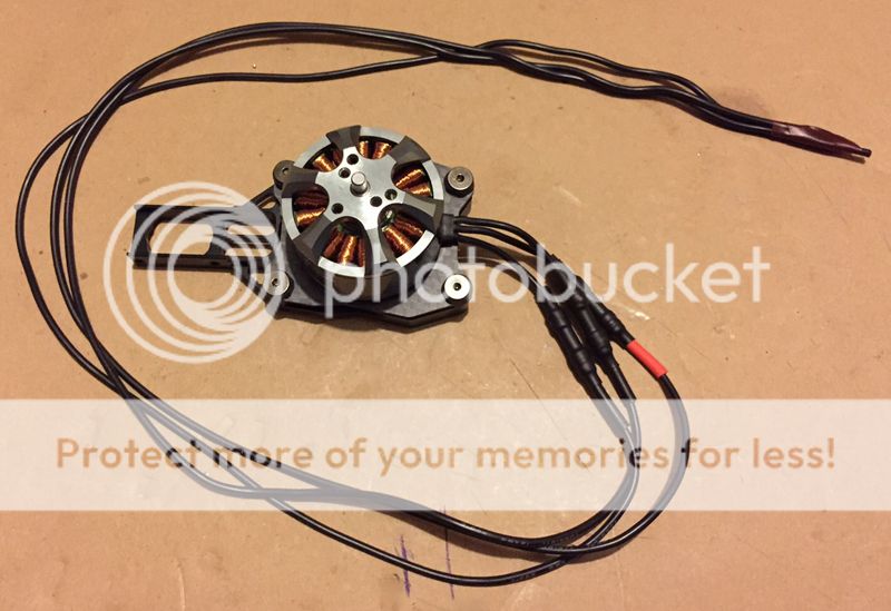
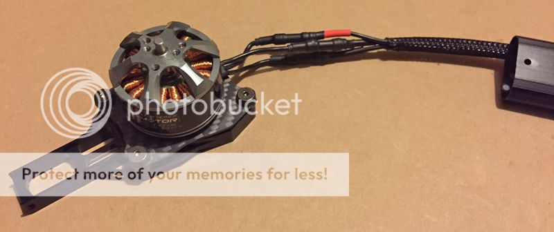
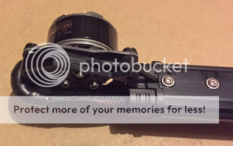
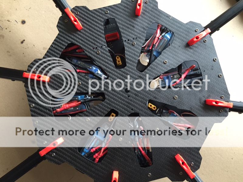
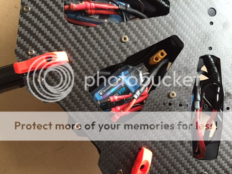
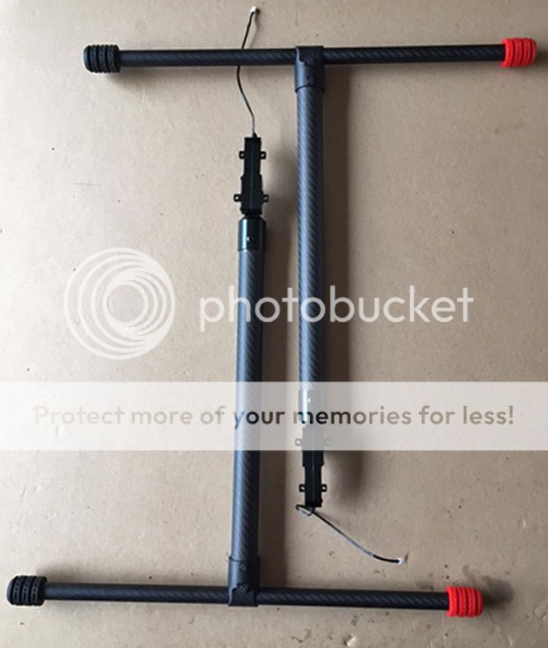
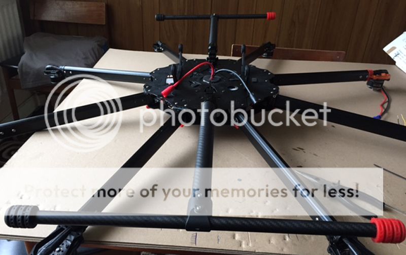
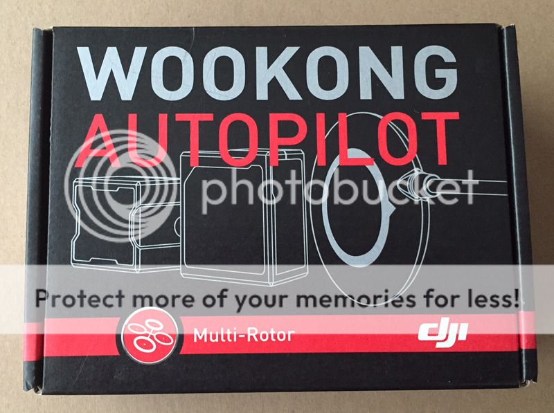
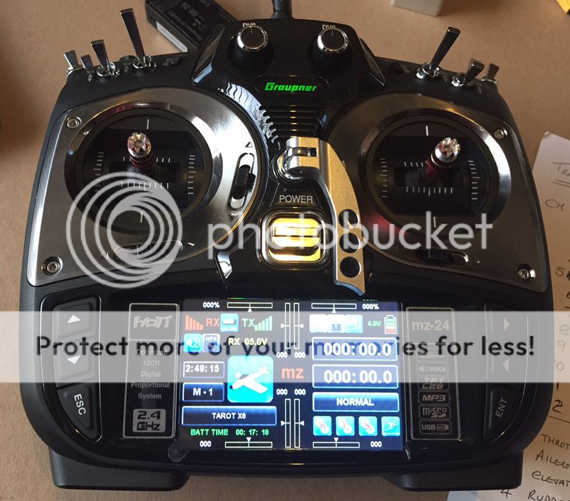
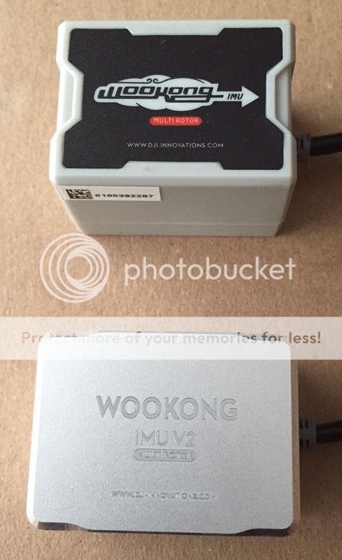
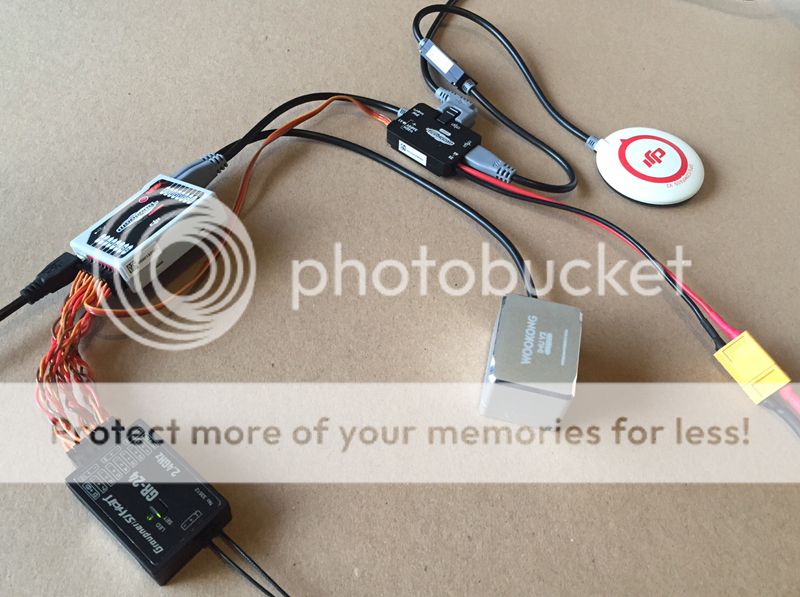
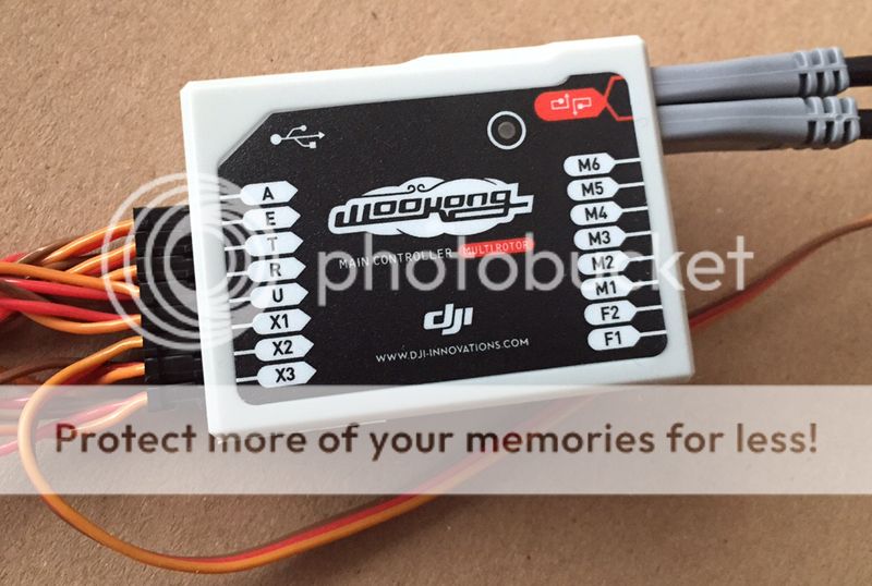
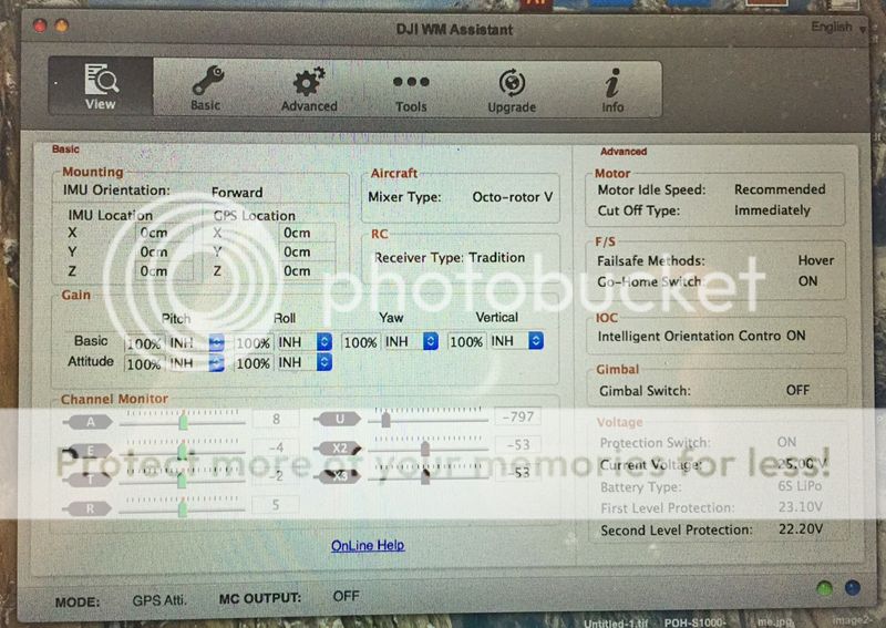
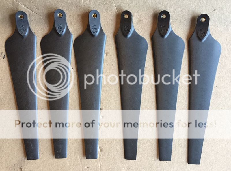
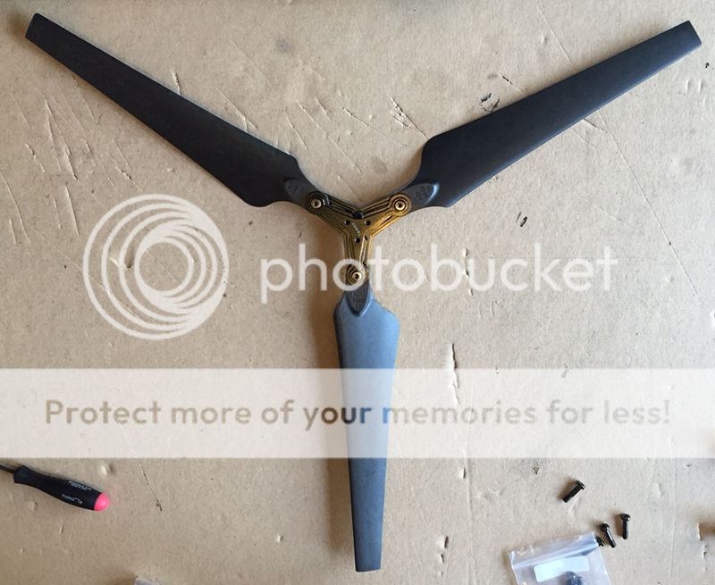
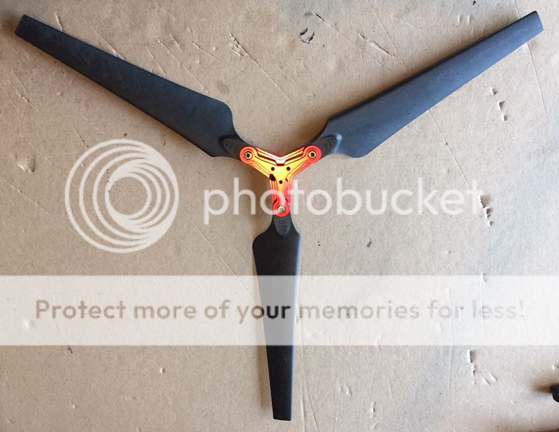
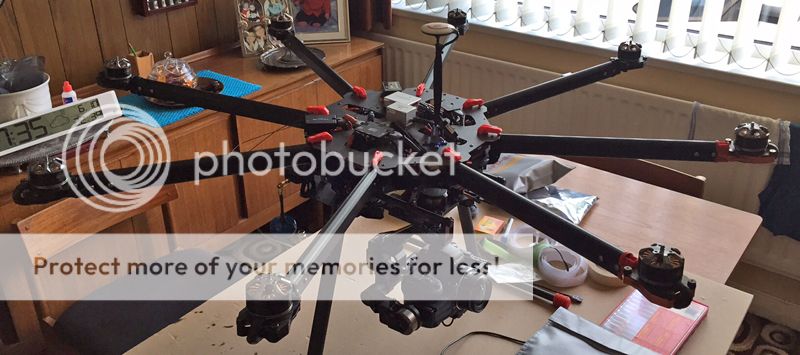
So I got the chance to buy a Tarot 960 complete with motors, Esc, wiring, retractabe legs, DJI Naza M v2 flight controller and GPS, props etc for a whole let less than buying new, this has been stripped and the DJI Naza M v2 will be changed for the DJI Wookong M, this will enable me to fit the fantastic DJI Zenmuse Z15-5D Gimbal.

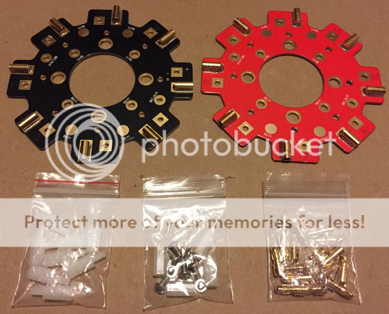
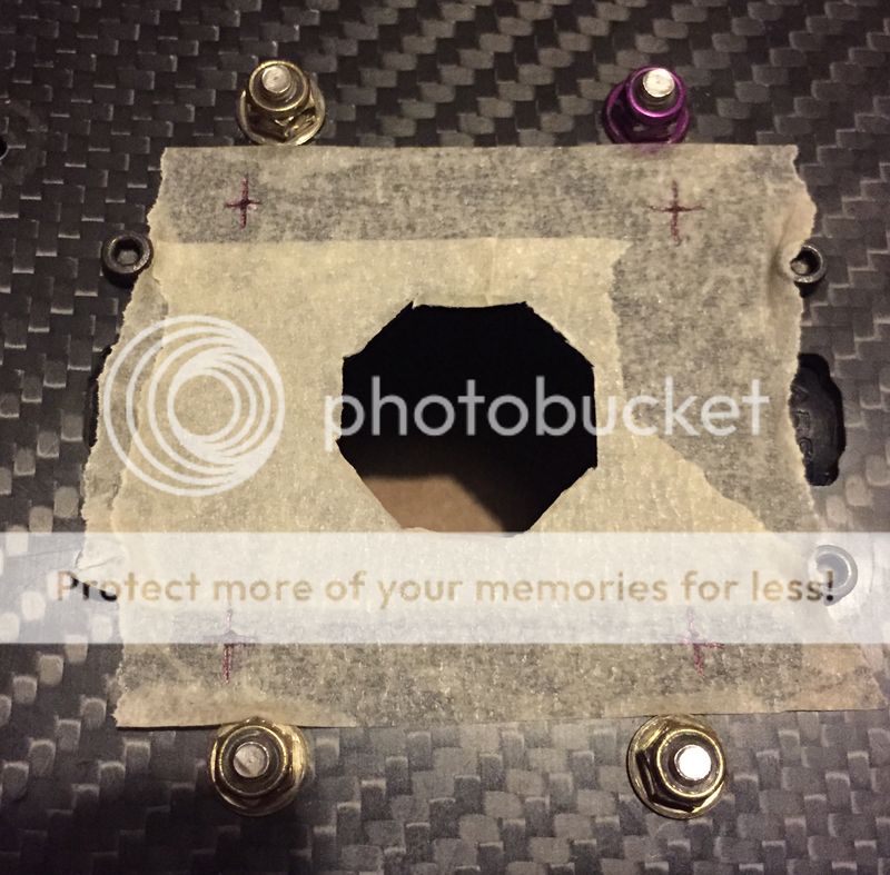
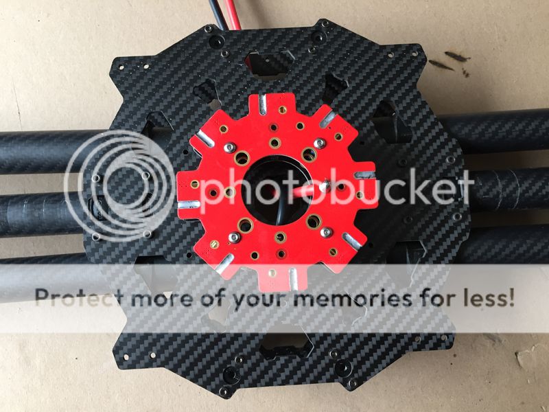
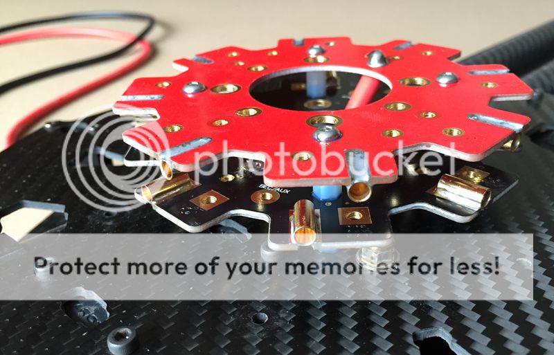
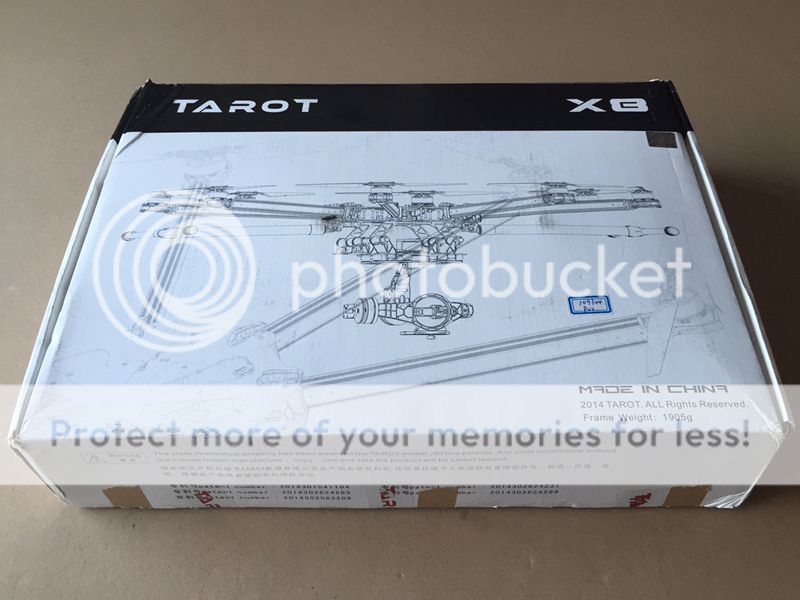
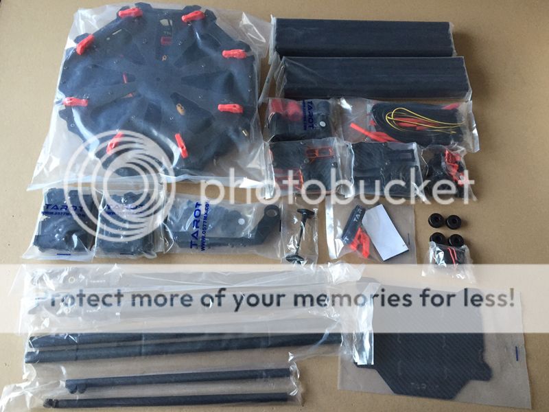
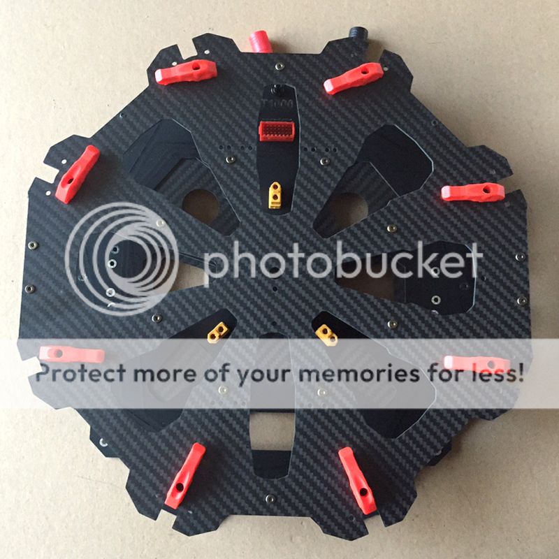
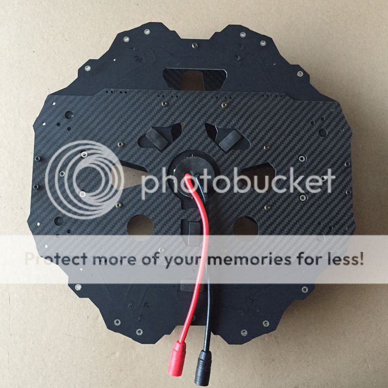
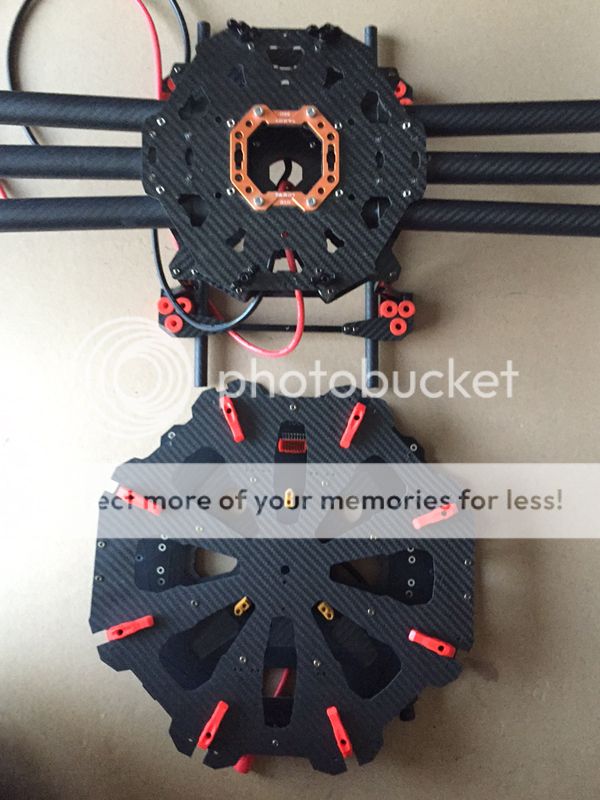
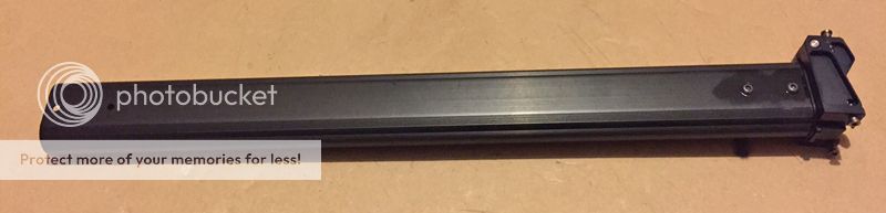
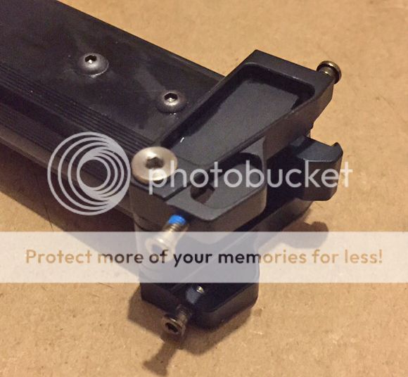
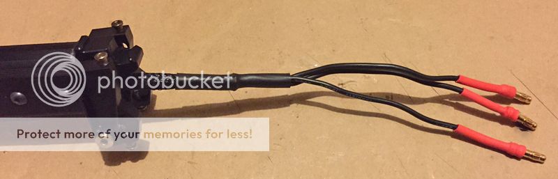
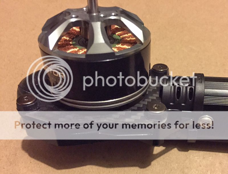
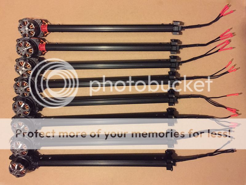
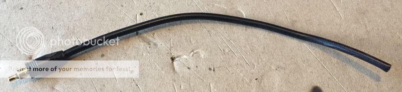
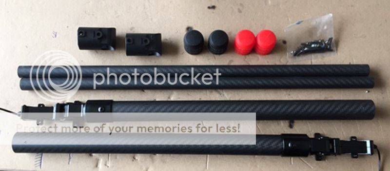
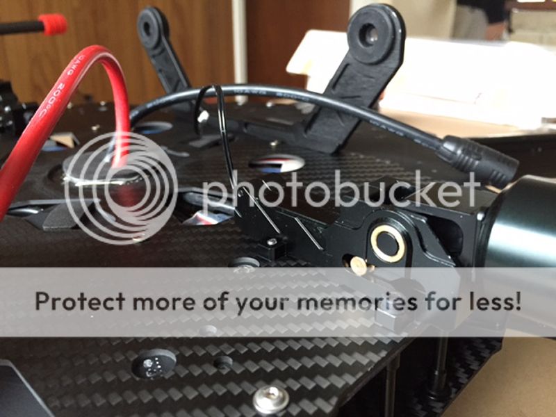
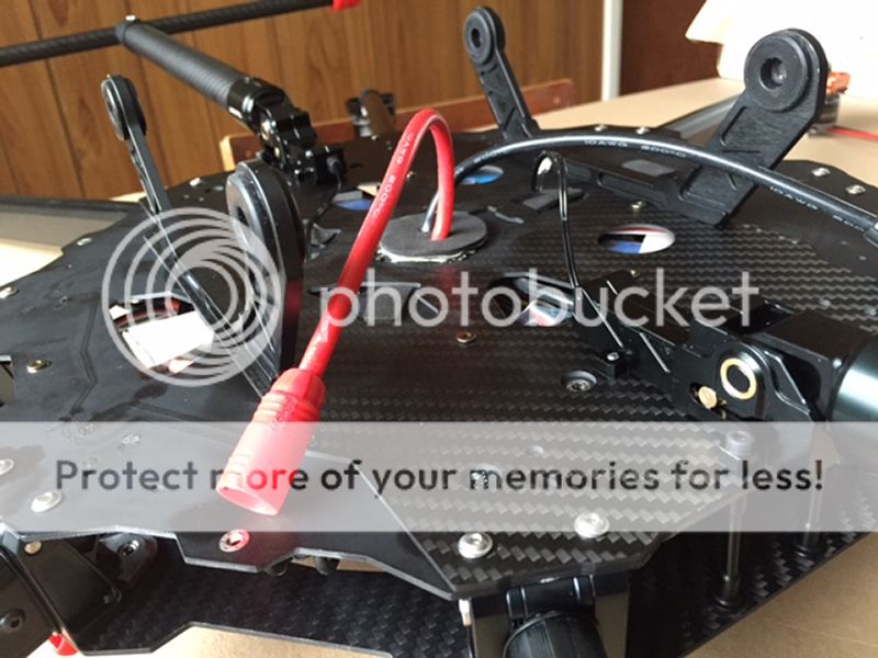
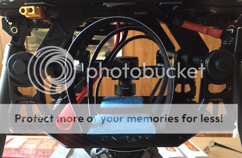
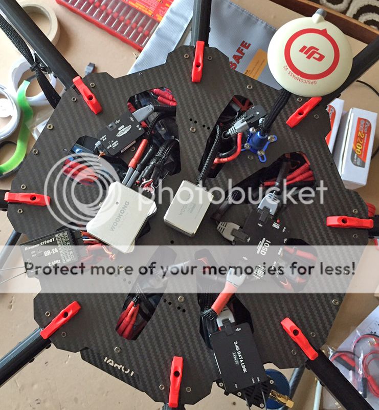
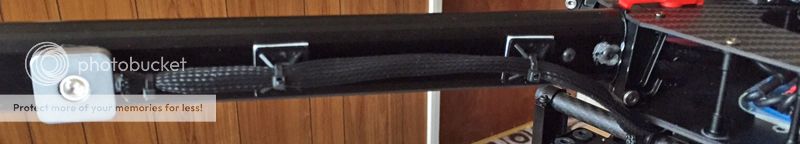
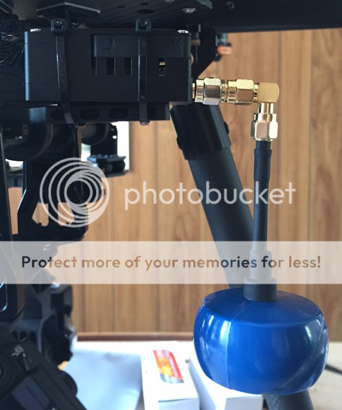
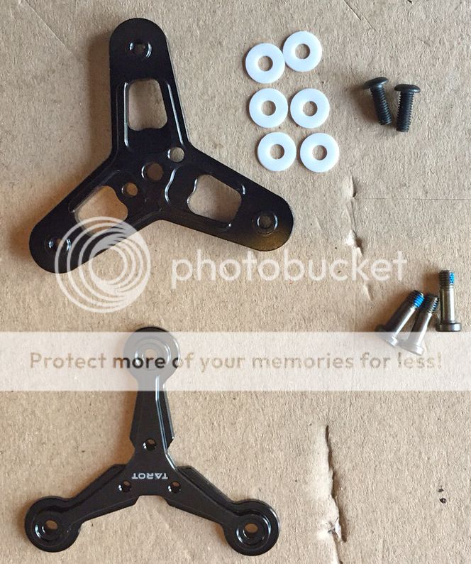
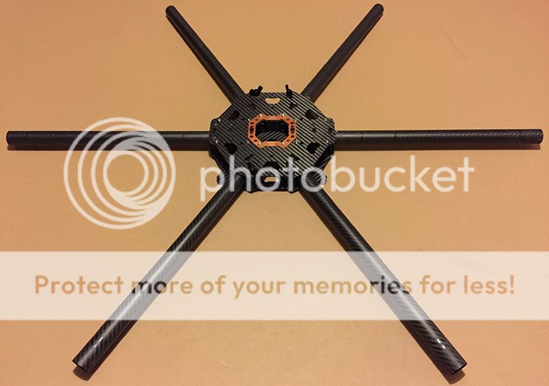
So the frame has been stripped of all its bits and bobs and wiring as I'm going to wire it better than it was, 1 reason for choosing the Tarot 960 frame is that being carbon fibre its very light and very very strong, and it can be closed up for transportation. Pics Below.

Tarot%20960%20Frame%20Open_zpsgamx19nf.jpg


Tarot%20960%20Frame%20Closed_zpsqfpcunlj.jpg


Link to Frame - http://tarot-rc-heli.com/Tarot-RC-M...i-Kits/Tarot_RC_T960_Multirotor_Copter_1000mm

On to the battery side of things I decided upon 1 large battery, instead of 2 smaller ones, as a survey of current users said you get longer in the air with the larger capacity battery.
Now charging a large LiPo battery is not as straight forward as bunging it on a charger and coming back 2 days later. the dedicated chargers and the current required to charge the battery is not small.
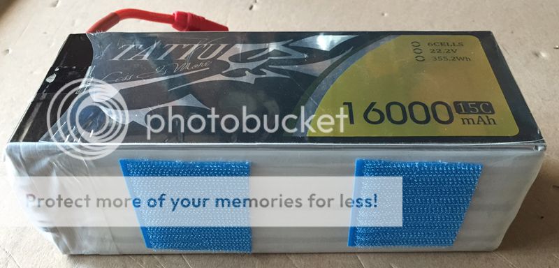
So as most chargers require a Dc voltage of between 10-30vDc sum up to 50vDC, a large power supply is required, 2 routes easily available are buy a charger and power supply readily available, or buy the charger and convert a Server power supply as these can deliver the current required. I got a server supply capable of delivering 12vDC and 175A but just couldn't live with the noise generated by the fans, so after some hunting around found a 12-24vDC variable 60A (1200W) power supply, and i coupled this with a charger, the iCharger 308DUO capable of charging 2 channels at a total of 1300W, the battery that got the most very good feedback and is respected in the heavy lift multicopter circle is the Gens Ace Tattu range, where i purchased the 16000mah 6S (22.2v) battery. If you think photography is expensive, time to think again.

Link to Power Supply - http://www.ev-peak.com/Titan_1200w.html

Link to Charger - http://www.progressiverc.com/icharger-308duo.html

Link to Battery - http://www.genstattu.com/tattu-16000mah-15c-6s1p.html

My plan is to keep updating the thread as the build goes on if there is interest in this.

Mark

PART 1 - https://www.talkphotography.co.uk/threads/uav-drone-hexacopter-build.581675/
PART 2 - https://www.talkphotography.co.uk/threads/uav-drone-hexacopter-build.581675/#post-6770366
PART 3 - https://www.talkphotography.co.uk/threads/uav-drone-hexacopter-build.581675/#post-6827723
PART 4 - https://www.talkphotography.co.uk/threads/uav-drone-hexacopter-build.581675/#post-6827738
PART 5 - https://www.talkphotography.co.uk/threads/uav-drone-hexacopter-build.581675/#post-6836017
PART 6 - https://www.talkphotography.co.uk/threads/uav-drone-hexacopter-build.581675/#post-6844559
PART 7 - https://www.talkphotography.co.uk/threads/uav-drone-hexacopter-build.581675/#post-6848164
PART 8 - https://www.talkphotography.co.uk/threads/uav-drone-hexacopter-build.581675/#post-6861691
PART 9A - https://www.talkphotography.co.uk/threads/uav-drone-hexacopter-build.581675/#post-6901031
PART 9B - https://www.talkphotography.co.uk/threads/uav-drone-hexacopter-build.581675/#post-6901033
PART 10A - https://www.talkphotography.co.uk/t...updated-11-june-15.581675/page-2#post-6909202
PART 10B - https://www.talkphotography.co.uk/t...updated-11-june-15.581675/page-2#post-6909204
PART 11 - https://www.talkphotography.co.uk/t...updated-17-june-15.581675/page-2#post-6919470
 
Last edited:
You will love it... till it crashes, then you will cry... like a little girl... I did ;)
 
Sounds like a great project. I'm looking forward to seeing your updates and following your progress.

Good luck with the build.

Chris
 
  • Like
Reactions: mho
This could get very interesting. I'll be watching this thread. Good luck.
 
  • Like
Reactions: mho
Very interesting! Subscribed.

I've just got into the aerial stuff and bought a Phantom 2 and an Inspire 1. Great fun.
 
  • Like
Reactions: mho
PART 2

Not a massive update to the build today, I haven't had time to get on it.

My next port of call was to decide upon how it was going to be wired, originally everything was wired in 16AWG silicone cable and all joints soldered, which looked good but threw up some points i needed to address, if a component need changing a lot of soldering would need to take place, and some of the joints were hard to find. I decided upon fitting a high current power distribution board, this was the main power from the battery would be 10AWG silicon cable soldered to the PDB - Power Distribution Board. and everything else would plug in using 3.5mm gold bullet connectors, after some looking around i found a PDB capable of carrying 260 amps continuous and a massive 320 amps peak, this would be enough for the hexacopter and ancillary's. I purchased a PDB for an octocopter this gives me the 6 outs for the ESC's but also 2 spare outs for the controller and other ancillary items.

Kit which builds up into the PDB.
Power%20dist%20components_zpsis2hl0ku.jpg


Next was where to mount it, the obvious place was under the main bottom centre board, as there would be plenty of clearance from the gimbal and the 2 layers of carbon fibre would help shield the controllers which would go on the top board.

Holes marked out ready for drilling.
Power%20dist%20markout_zpsrmksxgfk.jpg


After drilling all the holes everything was test fitted to make sure all was well, then stripped down again, the 10AWG silicone cables were then soldered to their respective solder tags, then everything was reassembled using Blue thread lock on all the screws, this allows them to be undone if required, but stops them being undone due to vibration.

A couple of images of the fitted PDB.

Power%20dist%20mounted_zps7qqnckrh.jpg


Power%20dist%20mounted%20side%20view_zpsphntzqxq.jpg


Next time fitting the ESC's.
 
Part 3


Hi, unfortunately not a lot is happening to the build, most of my time is being taken up with my picture framing business, hopefully i will have some time in the near future.

My latest job was to put the battery / gimbal frame onto the bottom of the main body, as it name suggests this would carry the battery on the top side and the gimbal will hang from the bottom of the frame work.

image12_zpslwioycjo.jpg


As you can see the gimbal has damping from the red rubbers that separate the 2 rails from the main body of the UAV,this will hopefully eliminate any vibration being passed to the rails, if the rubbers are too soft i can change them for a stiffer set. The frame legs are made from Aluminium and everything else carbon fibre, it is a very stiff and solid build.
 
Last edited:
Part 4


Hi, well quite a major development has taken place, and after a lot of head scratching and brain hurt, I have decided to convert the build to carry 2 GoPro 4K cameras for a 3D system, but i still need a UAV to carry my 5Dmark2, so after some searching around I acquired a Tarot X8 folding frame. I decided to change to this frame as the 8 arms gave me some redundancy in motors and lift capabilities, ie, if i had a motor or Esc fail it wouldn't compromise the safety of the unit in any way, i believe i could have 2 fail and it would still fly. The Tarot X8 pays homage to the DJI S1000, in its style and folding capability's, something else which appealed to me.

So below are some pictures of the Tarot X8 just as im unboxing it for the first time.

Not very interesting just the outer box.

image22_zpsfjl4tid5.jpg


Shows the contents of the box nearly every part is either cnc aluminium or carbon fibre

image41_zpsrjnuyvnw.jpg


The interesting bit, the centre unit, with power distribution and signal distribution all embedded within the bottom fibreglass plate, which is
reinforced with carbon fibre.

image61_zpsrzb37tq1.jpg


Showing battery connections leading to integrated power distribution.

image51_zps69pk5vbb.jpg


Shows the massive centre plate size of the X8 against the T960.

image71_zpsyg3dae6s.jpg


I have added 2 more T-motor 4014-11 motors and 2 more DYS 40A opto ESC's ready to start building.

I will be building the Tarot X8 first then the T960.

More to come soon.

Mark
 
Last edited:
I've been looking forward to seeing your update!

Thanks i just cannot get the time on it i need but hopefully all that is changing this week, and with the new frame it will be an interesting time.

How you getting on with the inspire ?.
 
Thanks i just cannot get the time on it i need but hopefully all that is changing this week, and with the new frame it will be an interesting time.

How you getting on with the inspire ?.

I am not! I am doing all my flying with my Phantom 2. I have had my Inspire camera unit sent to DJI in Germany and the image quality is just not good enough. They've only had it 2 weeks so I'm not expecting it back yet. To fly the thing is awesome. I have literally just started writing my Operation Manual based around the Inspire, so need to get it in the air soon to get lots of practice under my belt for when I undertake the Flight Examination.
 
I am not! I am doing all my flying with my Phantom 2. I have had my Inspire camera unit sent to DJI in Germany and the image quality is just not good enough. They've only had it 2 weeks so I'm not expecting it back yet. To fly the thing is awesome. I have literally just started writing my Operation Manual based around the Inspire, so need to get it in the air soon to get lots of practice under my belt for when I undertake the Flight Examination.

Sorry to hear its had to go to DJI, hope its back soon. Good luck with the flying and the Examination.

The Operations manual is quite a tricky one, ive been looking at a few and they are very comprehensively written, but i think if you know your aircraft it shouldn't be too hard a task.
 
Sorry to hear its had to go to DJI, hope its back soon. Good luck with the flying and the Examination.

The Operations manual is quite a tricky one, ive been looking at a few and they are very comprehensively written, but i think if you know your aircraft it shouldn't be too hard a task.

Thanks, and I'll let you know!
 
  • Like
Reactions: mho
Part 5

Well what can I say, summer has been and gone !, and Ive had some time to get a few bits done on the UAV build, First job as to get the aluminium tube and the CNC'd aluminium joint pushed together and secured with the M3 cap screws complete with a dab of thread lock (every screw is getting a bit), 4 of the arms and joints when together very easy the remaining 4 were a total %$&*£, after a lot of swearing and brute force they were persuaded together, screws and thread lock on and 8 arms with folding joints done.

image31_zpsck6mxckh.jpg


Shows close up of the joint and arm, this allows the arms to fold down when being stored or transported.

image41_zpsd7je6ntp.jpg


Next was to mount the motors onto the motor mounts, again aluminium and carbon fibre, these incorporated motor damping between the carbon plate and the aluminium mount, very well made and machined. Motors secured using M3 Stainless cap screws 6mm long, with thread lock on all threads.

image22_zpszwakgvqm.jpg


Extending the wires to run through the arms and joint, into the main frame where I have decided to place the ESC's. I decided upon this location as the centre plate is massive the ESC's will be on the lower plate, under the top plate which will have all the flight controller etc. The X8 has been designed to house the ESC's within the arms near to the motors, but in doing this if an ESC when wrong you would have to strip the arm down to sort the problem, plus you would have to add capacitors the the front end of the ESC's to help minimise power spikes on the long incoming leads to the ESC which in time will damage them.

I have left the connectors on just incase a motor needs changing it can be done by just unplugging instead of un-soldering, all joints are secured with heat shrink

image12_zpshgnnfl6d.jpg


As the wires are running through the aluminium and the joint, they will be placed inside a teflon coated braided tubes to protect them this will be secured at the motor end with amalgamating tape to protect the wires as they leave the motor. The ESC end will be terminated using heat shrink. the process of threading the wires and braided tube through the joint and arm is not to be underestimated, the hole on the joint for these to pass through is about 5mm x 7mm oval and very tight, lots of fun was had, but I got there in the end, $ done and 4 left to go, guess what im doing on Saturday afternoon when i get home from the shop.

Shows braiding and motor connected before braiding is moved over connectors and wrapped

image51_zpsrd7vvf7z.jpg


Braiding over cable joints and wrapped in amalgamating tape.

image71_zpsa2plmse3.jpg


Completed end with connectors soldered and heat shrink applied and cables braided.

image9-_zpss8wxzeos.jpg


Shows the plastic ends which finish the aluminium tube and motor mount end.

image81_zpslvqd4uys.jpg


So i have 4 more to make up then on with the next bit.

NOTE, some of the dome head screws in the kit are not of good quality and are soft, that is why i have bought some Stainless Steel dome head flanged M3 6mm cap screws, the hex part doesnt round off like on the cheaper screws in the kit, they will all be substituted for these.

thanks for reading.
 
Last edited:
Looking good so far, the Tarot frames really look fantastic and it's top of my purchase list
 
  • Like
Reactions: mho
Looking good so far, the Tarot frames really look fantastic and it's top of my purchase list

The new Tarot X4, X6, X8 are a great design, and the centre plate is just massive, you can see the difference between that and the T960 in the photos, don't get me wrong the T960 will be getting built but for a lot smaller cameras.

My biggest complaint is that the metal the screws are made from is very soft and when tightening them up you run the risk of rounding them off, that's why ive been changing them for A2 Stainless Steel ones.
 
Last edited:
Part 6

I managed a few hours the other night after waiting 3 days for a load of 3.5mm gold bullet connectors to arrive, so i finished the 8 arms off and they are all done.

image1_zpsjbtpjpjd.jpg


Next was to make the cables for connection of the ESC's to the main power distribution hub, as im not putting the ESC's in the arms, but installing them on the lower centre deck, i needed to cut down the cables which have a small coaxial connector on them for plugging into the power distribution box.

Cut down cable
image6_zpsticxi7yd.jpg


Connector for connection to power distribution
image2_zpsz61g528w.jpg


Next was to strip the cut end, tin with solder and insulate with heat shrink ready for the 3.5mm gold bullet connectors.

Stripped, tinned and heat shrinked ends
image5_zpsu2tysg1w.jpg


All left now solder the 3.5mm bullet connector on and heat shrink over

Bullets soldered and heat shrinked.
image4_zps1q5z7gos.jpg


All 8 done
image3_zpssfa4frqe.jpg


Next time fitting ESC's, Motor arms and connection cables.

thanks for looking

Mark
 
This looks like a very professional construction - good work.

Please keep feeding us with updates.

Chris
 
Part 7

Hello again, so some building went on today after work with the arms and motors fitted to the centre plate, and the Esc's being fitted and wired, along with landing gear assembly and fitting.

SO the arms and motors were secured to centre plates with 4 screws each all thread locked, after eight of these were done I came to one conclusion, this is massive, even though you know the size, its not until you get it infront of you in person that you really see how big it is.

Next was to fit the ESC's in between the 2 centre plates, connect them up and connect the signal wire. Connections were all connected, but no heat shrink applied over the joint, just incase we have to change motor direction or replace a faulty ESC's.

Shows all eight ESC's connected between centre plates
image4-_zps31nrnwqh.jpg


Close up of ESC
image3-_zps1086xobd.jpg


Next up was the landing gear, as shown below comes in a few parts but nicely fits together
image5-_zpsv3wabctx.jpg


Fully assembled and ready to fit, note rubber bumpers on end of landing gear, tubes are 25mm and 15mm carbon fibre
image6-_zpshledqzg8.jpg


Retracts fitted to the bottom of the centre section, 3mm bolts for fixing along with a dose or threadlock.
image7-_zpsqimlj1q6.jpg


Close up of retracts
image8-_zpsabv47r0x.jpg


Close up of the under part of the centre section show 8AWG battery cable to power distribution,
showing brackets for gimbal and battery
image10-_zps3ffdsqj3.jpg


next time retract wiring and then all the electronics

thanks for looking

Mark
 
Enjoying this thread. Thanks for keeping us updated.
 
  • Like
Reactions: mho
Part 8

Hi everyone, I'm sorry for the delay in posting but with work, and having to get to grips with configuring and programming the transmitter its taken a while.

I have been concentrating on getting the transmitter and receiver programmed and connected up to the flight control system, I chose, DJI's Wookong-M flight controller and GPS system as its tried and tested , and constantly being updated via firmware updates, for the transmitter and receiver I decided to go away from the normal Spektrum or Futaba systems and use the Graupner MZ-24, this has 12 channels which are all capable of being configured to do whatever you need them too, and its a cracking deal, as it comes with a 12 & 6 channel receiver, case, charger, SD card, usb cables for firware updates etc, making it a great setup,

Wookong-M
image4_zpsbvyvt5no.jpg


Graupner MZ-24 12 channel transmitter
image2_zpskwghvkz2.jpg


Graupner 12 Channel receiver
image6_zpsyzcgltx1.jpg


A bit about the Wookong M, it comes in a few versions, version 1, then they upgraded the GPS to version 2, and finally they have upgraded the IMU to version 2, which is a upgrade part with the original IMU needing to be returned to DJI, (this is a paid upgrade not free) luckily i managed to get one from Germany that didn't need my v1 IMU sending back. The upgrade helps with stability on heavy lift Hex or Octo builds.

V1 & V2 of the Wookong IMU
image5_zpsax8mxf7w.jpg


So now its time to connect everything up and bind the receiver to the transmitter in order to calibrate the transmitter to the wookong and set all the switches up for your desired functions, which apart from the 4 main control channels, 3 position mode switch, 2 position fail safe switch, 2 position standby, go home switch, 3 position Intelligent orientation control switch, landing gear up down switch, and setting up fail safe in case transmitter signal is lost. so after lots of reading and messing about experimenting I connected the wookong software up and started programming the set-up, quite a few hours later all was done (I HOPE). All functions were tested with the software and look to work how they should.

Wookong all connected ready for testing / setup
image3_zpsxzdg0ldg.jpg


Wookong Controller close up
image7_zpshkuh0obo.jpg


DJI Wookong M setup software
image1_zpsszwbetai.jpg


Thanks for looking, any questions please feel free to ask.

Mark
 
I see you have gone traditional on the receiver, why did you not go for cppm, can you not get a cppm signal out of the graupner?

I've been flying frsky and to be honest haven't had a look at the graupner system. The radio looks like a nice bit of kit.

EDIT: Just had a look at the MZ24 - That is one serious bit of overkill ;)
 
Last edited:
I see you have gone traditional on the receiver, why did you not go for cppm, can you not get a cppm signal out of the graupner?

I've been flying frsky and to be honest haven't had a look at the graupner system. The radio looks like a nice bit of kit.

EDIT: Just had a look at the MZ24 - That is one serious bit of overkill ;)


As i want to use the remaining channels as traditional outs,
when in PPM all channels are sent to the wookong down the one cable as far as i understand from the manual (I maybe wrong)
At the price I paid for the Graupner its outstanding value for money, especially with the 2 receivers included.
wasn't worth paying more for something else.
 
Correct, I believe (it's been a while since I set up my Naza V2 but I think the principles are the same) you connect up cppm/ppm to X2 and this gives you full control of the FC on a single signal lead, you can then use the remaining traditional channels to control external devices, lights, gimbal override, leg retracts etc.
 
I didnt know the remaining channels could be used as traditional when using PPM to the Wookong, the manual, seems to read as it cannot, I will have to have a go see what happens.
 
I didnt know the remaining channels could be used as traditional when using PPM to the Wookong, the manual, seems to read as it cannot, I will have to have a go see what happens.

It's the transmitter/receiver combo that should allow it not the Wookong Mark ;)
 
It's the transmitter/receiver combo that should allow it not the Wookong Mark ;)

Yes i know that, but from the manual (for graupner) it seems to say that when using PPM you cannot use the remaining outs from the receiver as traditional channels, as all channels are output at channel 8 which has to be used as the connection to wookong when using PPM.
 
Yes i know that, but from the manual (for graupner) it seems to say that when using PPM you cannot use the remaining outs from the receiver as traditional channels, as all channels are output at channel 8 which has to be used as the connection to wookong when using PPM.

It looks like its a receiver limitation then, being as its a 12 channel receiver I think you made the right choice going the way you did then.
 
It looks like its a receiver limitation then, being as its a 12 channel receiver I think you made the right choice going the way you did then.

Just had another look at the manual and it maybe possible to set the PPM out on channel 8 and set so that PPM is used only on the first 8 channels leaving the remaining 4 channels to be used as traditional channels, I will investigate one night this week.
 
I changed it over to PPM and set up the Tx/Rx to SUMO 8 and receiver is connected with 1 cable to output 8 so channel 1-8 are mapped to Wookong using PPM, and outputs 9-12 are usable as traditional outputs. All works well, so im pleased with that outcome, its just a pity the manual doesn't clearly say you can do it that way.
 
Last edited:
Part 9A

Sorry its been such a long time, I have got quite a bit done in the time since the last update, a lot of time was spent on getting the right layout and some of the components were not how i wanted them so sourcing replacements has taken time, (Slow boat from china). Also programming the transmitters and fine tuning the set-up has been interesting to say the least.

I decided to braid up all of the cables for the flight system as they come in very close contact to the edges of the carbon fibre, and didn't want to take any chances with any wearing through. So all braided with a Teflon coated nylon braid.

First up was fitting the battery tray and gimbal as they share a common mounting rail. first problem i encountered was I could not fit my big (20000mah) battery on the tray it hit the body of the UAV, I sourced some linger mounting brackets again Tarot made and now the battery fits perfect. Also added was Velcro to stop battery slipping and straps to keep it in place.

Shows battery tray, longer brackets, Velcro and straps, also shows the AS150 Anti-spark connection (red) and the XT150 (black)
image12_zpsylrhf7zy.jpg


Small battery with Velcro
image13_zpssst0ntaw.jpg


Next was to attach the gimbal and wire in the receiver for it, again wired in PPM mod.
controls include, Pan, Roll, Tilt, 360 Pano photo mode, video start stop, shutter, camera straight down, mode switch and a dual rate switch to slow gimbal travel speed by 50% on all axis.

Side view with transmitter connected to GMU on gimbal, Canon 5D2 with 24mm IS f2.8 lens in the gimbal
image8_zpshcrcxxlq.jpg


Front view, (note my iphone has distorted the photo everything is nice and square on the mounting brackets)
image9_zpsmiw0sf2l.jpg


Next was to attach all the flight control, GPS antenna, PMU, IMU, Wookong FC, receiver, ground-station, can bus hub.
IMU was sat on s piece of vibration absorbsion gel, all other items were sat on foam. to help stop vibrations if any occur.

Top layout of FC conponents, GPS antenna folds flat for storage.
image10_zpsmyr3ewbi.jpg


Status LED secured to arm
image7_zpsaqwgntpt.jpg


Next was the DJI AVL58 5.8ghz transmitter, this was bracketed off the battery rail, the stock antenna was replaced with a
VAS Air Screw circular polarising antenna designed by the legendary IBcrazy.

image11_zpszppv92mk.jpg
 
Last edited:
Part 9B

Next was to the propellers, i had decided on folding ones for ease of storage and transporting the UAV. The logical option was to use DJI's folding blades they have on their S1000, as the tarot x8 is of a similar design and weight. I had initially decided to go with a 2 blade conventional system per motor, but after a lot of research I decided upon a 3 blade approach, for a few reasons, due to being limited to 15" diameter blade area, it transpired that the extra blade on each motor would give me approx 15-20% extra thrust, with only a 3% loss in efficiency, numbers which i was willing to take, effectively the 3 blade system was equivalent to a 16.5" 2 blade set-up. 3 Blade hub was purchased from Tarot due to price, availability and weight. (again on the slow boat from china)

3 blade hub
image4_zpsupd2hdlw.jpg


DJI folding blades CW & CCW 1552 blades
image3_zpsqtyqlwxw.jpg


An assembled CW propeller set
image2_zpsikhgfmr5.jpg


An assembled CCW propeller set
image1_zpsdp9ugkdw.jpg


Here is the open frame and closed for transport.

image6_zpsunumiqri.jpg


image5_zpsm3nqdqri.jpg


Well not much left now, some work on the transmitters, and to set-up the monitors from the 5d2 so both pilot and camera man have live feeds and data feeds from the camera, a test flight and then a shake down / installation session. and build a transportation case for everything.

thanks for looking hope your enjoying it all, not long now till its finished.
 
Last edited:
Back
Top