


- Messages
- 90
- Name
- Andreas
- Edit My Images
- No
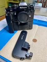
A very useful accessory for the Nikon MD-4 Motor Drive for the Nikon F3 is the Nikon MK-1 Firing Rate Converter, which is mounted underneath the motor drive.
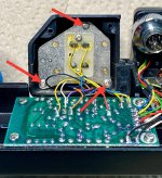
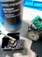
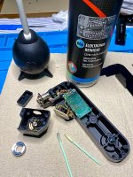
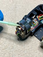
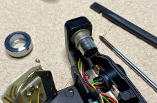
In the following post, we’ll take a look at how to service it—for example, if contact issues arise, which are the most common cause of electronic problems in camera equipment from that era.
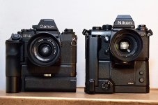
Two flagships and rivals of the 1980s:
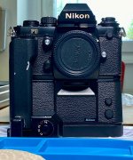
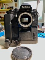
Canon New F-1 with Motor Drive FN and Nikon F3 with MD-4 and MK-1, which is mounted below the motor drive.
The Nikon F3 and its exclusive motor drive MD-4 are a perfectly matched pair.
The MD-4 not only cocks the shutter and transports the film, but also makes the F3 more comfortable to hold.
In continuous (C) mode, the MD-4 speeds up the film to 5.5 fps (frames per second), powered by eight AA batteries.
Nikon MK-1: Speed control and shutter release in portrait format
However, you don't always need that much speed, so the Nikon MK-1 firing rate converter is the third in the group.
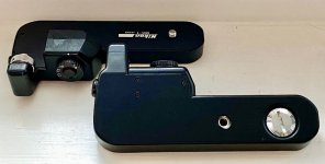
It reduces the film transport speed to either 1, 2 or 3 fps or leaves it at 5.5 fps. It also offers a second shutter release with which the F3 can be conveniently fired in portrait format.
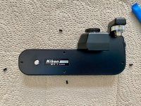
The MK-1, which is fixed to the underside of the MD-4 using two screws, does not require additional batteries.
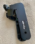
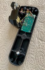
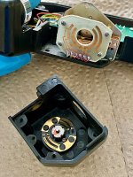
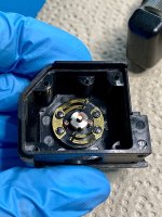
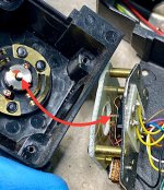
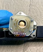
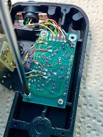
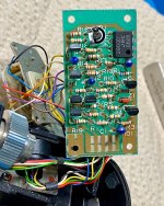
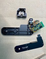
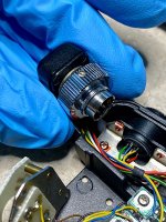
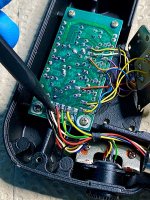
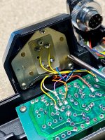
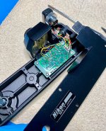
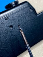
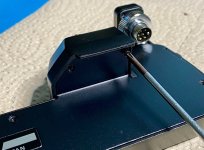
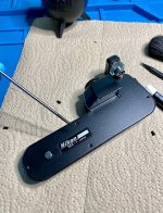
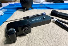
A look inside and repair of the trigger
The MK-1 is an accessory that is mainly made of metal just as solidly as the F3 and MD-4.
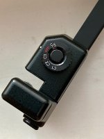
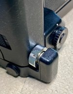
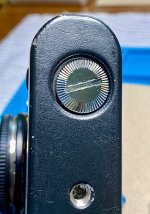
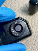
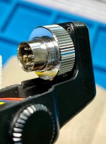
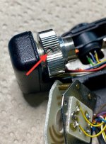
Nikon MK-1, control wheel with shutter release in the middle:
Set the motor speed to 1 frames per second (C1), 2 fps (C2), 3 fps (C3) or film transport at full speed of 5.5 fps (C/S).
OFF locks the shutter release, the film transport speed remains at 5.5 fps provided by the MD-4.
I own a few of these, some of them heavily used, which do their job perfectly.
However, the shutter release on one of them no longer works reliably.
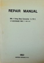
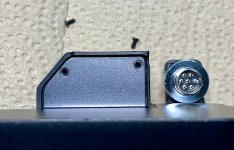
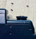
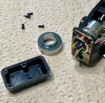
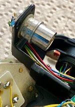
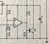
A good opportunity to take a look inside the MK-1 and familiarize yourself with the Nikon Repair Manual for the MK-1. It is the only service/repair document I am aware of for the MK-1.

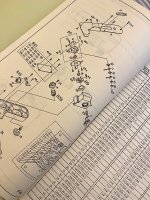
I was able to acquire the only one (original, no reprint) that was offered on eBay some time ago.
See also:
Nikon MK-1 firing rate converter instruction manual, PDF user manual (butkus.org)
In the following post, we’ll take a look at how to service it—for example, if contact issues arise, which are the most common cause of electronic problems in camera equipment from that era.
Two flagships and rivals of the 1980s:
Canon New F-1 with Motor Drive FN and Nikon F3 with MD-4 and MK-1, which is mounted below the motor drive.
The Nikon F3 and its exclusive motor drive MD-4 are a perfectly matched pair.
The MD-4 not only cocks the shutter and transports the film, but also makes the F3 more comfortable to hold.
In continuous (C) mode, the MD-4 speeds up the film to 5.5 fps (frames per second), powered by eight AA batteries.
Nikon MK-1: Speed control and shutter release in portrait format
However, you don't always need that much speed, so the Nikon MK-1 firing rate converter is the third in the group.
It reduces the film transport speed to either 1, 2 or 3 fps or leaves it at 5.5 fps. It also offers a second shutter release with which the F3 can be conveniently fired in portrait format.
The MK-1, which is fixed to the underside of the MD-4 using two screws, does not require additional batteries.
A look inside and repair of the trigger
The MK-1 is an accessory that is mainly made of metal just as solidly as the F3 and MD-4.
Nikon MK-1, control wheel with shutter release in the middle:
Set the motor speed to 1 frames per second (C1), 2 fps (C2), 3 fps (C3) or film transport at full speed of 5.5 fps (C/S).
OFF locks the shutter release, the film transport speed remains at 5.5 fps provided by the MD-4.
I own a few of these, some of them heavily used, which do their job perfectly.
However, the shutter release on one of them no longer works reliably.
A good opportunity to take a look inside the MK-1 and familiarize yourself with the Nikon Repair Manual for the MK-1. It is the only service/repair document I am aware of for the MK-1.
I was able to acquire the only one (original, no reprint) that was offered on eBay some time ago.
See also:
Nikon MK-1 firing rate converter instruction manual, PDF user manual (butkus.org)
Last edited:
 A word of caution


